
User Manual


SPEEDCOM SC5800 User Manual
31
4.4 Interconnection Cable Installation
Follow these steps to install the Indoor Unit to Outdoor Unit interconnection cables.
CAUTION
-
DO NOT OVER TIGHTEN THE CABLE STRAPS ON THE CABLES AND DO
NOT FASTEN THE STRAP LOCKING MECHANISM OF THE CABLE STRAP
ONTO THE CABLES.
1. On the OU side, connect an RJ45 plug to the data cable. Place the RJ45
plug into the RJ45 socket in the Outdoor Unit connection box.
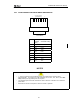
2. On the OU side, connect the DC power leads within the Outdoor Unit
Connection Box. Use the +Ve and Return connections.
18
Return +Ve "Chassis"
RJ45 Socket
3. Close the Outdoor Unit Connection Box Cover using a 2.5mm Allen key.
Make sure the rubber gaskets seal correctly over the power and data cables.
4. Using cable ties, secure the cable to the pole at regular intervals.
5. On the IU side, connect an RJ45 plug to the data cable. Place the RJ45 plug
into the RJ45 socket in the rear of the Indoor Unit.
6. On the IU side, connect the DC power leads to the supplied GREEN Phoenix
plug. Insert this plug into the green socket on the rear-panel of the IU.
7. The user can see that there is a suitable IU/OU data interconnection if the
‘IU/OU Link’ LED on the rear-panel of the IU is lit up green.
CAUTION
-
UNDO THE SCREWS OF THE “CONNECTION BOX” IN A UNIFORM
MANNER. THIS ENSURES THAT THE “CONNECTION BOX” GASKET
MATERIAL RELEASES STRESS UNIFORMLY AND DOES NOT LEAD TO
THE SECURING SCREWS BEING BENT DUE TO THE PRESSURE PLACED
ON THE CONNECTION BOX LID.