
User Manual

SPEEDCOM SC5800 User Manual
27
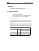
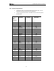
4.2.4 Balanced Payload Data
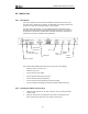
1. Assemble the (nE1) / (nT1) payload data input and output cable. See the
table below for Indoor Unit connector pin assignments.
2. Connect the payload data cable to the DB25 connector on the front panel of
the Indoor Unit.
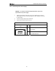
D-Type
Payload
Data
Connector
Pin #
Pin Name Tributary Direction
1 GND Earth N/A
2 RTIP1 1 RX +
3 RRING1 1 RX -
4 GND Earth N/A
5 TTIP1 1 TX -
6 TRING1 1 TX +
7 GND Earth N/A
8 GND Earth N/A
9 RRING0 0 RX +
10 RTIP0 0 RX -
11 GND Earth N/A
12 TRING0 0 TX -
13 TTIP0 0 TX +
14 TRING2 2 TX -
15 TTIP2 2 TX +
16 GND Earth N/A
17 RRING2 2 RX+
18 RTIP2 2 RX-
19 GND Earth N/A
20 TTIP3 3 TX-
21 TRING3 3 TX+
22 GND Earth N/A
23 RTIP3 3 RX+
24 RRING3 3 RX-
25 GND Earth N/A