
User Manual

Version 3.03 SPEEDLAN 9000 Series Installation and Operation User Guide
8-10 Using SPEEDView
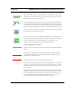
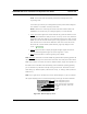
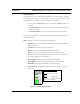
Top picture on left (noted as Fig. A) represents a Trace Route test. Trace Routes
are used for mesh networks only. For directions on how to create a trace route,
see Buttons (on the Main tab), page 8-12.
In a star topology, bandwidth on any given link is shown as a series of black
beads, as shown to the left. When the bandwidth beads are closer (as shown
in the bottom picture to the left as Fig. B), this indicates that more bandwidth is
being used. When these beads are further apart, less bandwidth is being used.
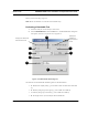
Blue, box outlines indicate that the node is selected. Solid green boxes indicate
that the node is the target of a trace route.
Solid, blue squares indicate which 9000 node SPEEDView is connected to. The
IP address of the node will be displayed on top of each node. You can display
the full IP address or part of it by selecting how many octets you want
displayed. For more information, see Options Tab, page 8-22.
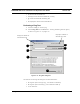
Can the nodes hear each other?
Green lines indicate direct line-of-sight connections between SPEEDLAN 9000
nodes.
Solid, red lines indicate that there is not enough signal strength to reliably
exchange data between the node pair, but some signal was detected on at
least one end of the connection.
Dashed, red lines indicate no signal between the node pair.
Red lines are used for debugging and adjusting antennas (e.g., who can hear
and why) in a star network. If a solid, red line appears, the system in a mesh
network could still use an indirect route or hop in order for the two nodes to
exchange data.
A redline without any signal level means that there is no direct communication
between the node pair in a mesh network. Data will automatically be routed
through the 9000 network in order for the node pair to communicate. It is a
user configurable option as to whether a dashed red line, or no line at all,
appears between the node pair without direct communication.
Beads
Bandwidth
Fig.
Fig.
A
B