
User's Manual
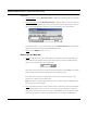
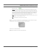
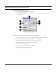
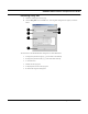
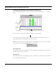
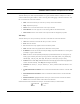
Table Of Contents
- Chapter 1 Introduction
- Features and Benefits
- Equipment Features
- SPEEDLAN K2's Polling Protocol -- How it Works in Star Networks
- SPEEDLAN 9000 Mesh Protocol -- How It Works in Non-Line-of-Sight Networks
- Chapter 2 Installing the SPEEDLAN 9101 & SPEEDLAN 9102 Hardware
- Rooftop and Tower Installations Warning
- Hardware Overview
- Drawings of Outdoor, Remote-Mounted Components
- The SPEEDLAN 9101 (with an Attached Standard Omni)
- The SPEEDLAN 9102 (with an External Antenna)
- Chapter 3 Using the SPEEDLAN 9000 Configurator
- Initial Configuration of the SPEEDLAN 9000
- Overview of the SPEEDLAN 9000 Configurator Main Menu
- Logging on to the SPEEDLAN 9000 Configurator
- Interfaces
- System
- Routing
- Wireless
- DHCP Server
- DHCP Relay
- NAT
- Diagnostics & Troubleshooting
- Administrative Access Pages
- Chapter 4 Using SPEEDView
- What is SPEEDView?
- System Requirements
- Installation Instructions
- Starting SPEEDView
- The Program Instructions
- The Main Tab
- Options Tab
- Admin Tab
- Chapter 5 Basics of IP Addressing
- Basics of IP Addressing
- Glossary for Standard Data Communications
- Glossary for Standard Data Communications
- Software License Agreement

SPEEDLAN 9000 Installation and Operation User Guide
Using SPEEDView 4-9
Represents a Trace Route test. Trace Routes are used for mesh networks only. For
directions on how to create a trace route, see, “Trace” under the Buttons (on the Main
tab), page 4-11.
In a star topology, bandwidth on any given link is shown as a series of black beads, as
shown to the left. When the bandwidth beads are closer, this indicates that more
bandwidth is being used. When these beads are further apart, less bandwidth is being
used.
Blue, box outlines indicate that the node is selected. Solid green boxes indicate that the
node is the target of a trace route.
Solid, blue squares indicate which 9000 node SPEEDView is connected to. The IP
address of the node will be displayed on top of each node. You can display the full IP
address or part of it by selecting how many octets you want displayed. For more infor-
mation, see Options Tab, page 4-19.
Can the nodes hear each other?
Green lines indicate direct line-of-site connections between SPEEDLAN 9000 nodes.
Solid, red lines indicate that there is not enough signal strength to reliably exchange
data between the node pair, but some signal was detected on at least one end of the
connection.
Dashed, red lines indicate no signal between the node pair.
Red lines are used for debugging and adjusting antennas (e.g., who can hear and why).
If a solid, red line appears, the system would still use an indirect route or hop in order
for the two nodes to exchange data.
A redline without any signal level means that there is no direct communication between
the node pair, and data will automatically be routed through the 9000 network in order
for the node pair to communicate. It is a user configurable option as to whether a
dashed red line, or no line at all, appears between the node pair without direct commu-
nication.
Beads
Bandwidth