
User's Manual


Version 3.03 SPEEDLAN 9000 Series Installation and Operation User Guide
2-10 SPEEDLAN 9101, 9102, 9103 & 9104 Hardware
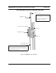
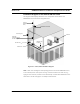
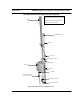
Installation Diagram of the SPEEDLAN 9101/9104
The diagram below displays where the main components are located for the
SPEEDLAN 9101/9104 with an integrated omni.
Figure 2-5: 9101/9104 installation diagram
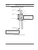
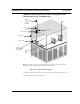
Note: Most users needing the mesh topology solution will use the SPEEDLAN 9101/
9104. However, there is the option of using an external antenna for mesh use (e.g.,
high-gain omni antenna, sectoral or even directional). Contact Wave Wireless for more
information. On the next page is an example of this solution:
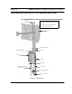
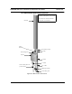
Antenna
(Integrated
omni)
SPEEDLAN 9101/9104
Grounding wire
Cable with
combined Ethernet
and DC voltage
AC wall outlet
Junction box
Ethernet / hub
Ethernet
or switch