
User's Manual
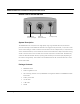
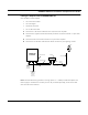
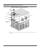
Table Of Contents
- Chapter 1 Introduction
- Features and Benefits
- Equipment Features
- SPEEDLAN K2's Polling Protocol -- How it Works in Star Networks
- SPEEDLAN 9000 Mesh Protocol -- How It Works in Non-Line-of-Sight Networks
- Chapter 2 Installing the SPEEDLAN 9101 & SPEEDLAN 9102 Hardware
- Rooftop and Tower Installations Warning
- Hardware Overview
- Drawings of Outdoor, Remote-Mounted Components
- The SPEEDLAN 9101 (with an Attached Standard Omni)
- The SPEEDLAN 9102 (with an External Antenna)
- Chapter 3 Using the SPEEDLAN 9000 Configurator
- Initial Configuration of the SPEEDLAN 9000
- Overview of the SPEEDLAN 9000 Configurator Main Menu
- Logging on to the SPEEDLAN 9000 Configurator
- Interfaces
- System
- Routing
- Wireless
- DHCP Server
- DHCP Relay
- NAT
- Diagnostics & Troubleshooting
- Administrative Access Pages
- Chapter 4 Using SPEEDView
- What is SPEEDView?
- System Requirements
- Installation Instructions
- Starting SPEEDView
- The Program Instructions
- The Main Tab
- Options Tab
- Admin Tab
- Chapter 5 Basics of IP Addressing
- Basics of IP Addressing
- Glossary for Standard Data Communications
- Glossary for Standard Data Communications
- Software License Agreement

SPEEDLAN 9000 Series Installation and Operation User Guide
Installing the SPEEDLAN 9101 & SPEEDLAN 9102 Hardware 2-15
Step 5. Grounding the Lightning Arrestor
a) Mount the lightning arrestor to a solid surface.
b) Run the grounding wire from the lightning arrestor to a proper ground source such as a
grounding rod or roof ground wire. The lightning arrestor is NOT waterproof.
Step 6. Weatherproofing Connectors
a) Seal the entire lightning arrestor with the black waterproof sealant insulation putty that is
included in the installation kit.
b) Apply two layers of electrical tape to the connector, and leave approximately 3 inches of
cable exposed on either side of the connector. An alternative is to begin at the lowest point,
so the tape overlaps from bottom to top creating a shingled effect. (This creates an effective
barrier against water runoff). Apply this "shingle effect" to each layer of the sealing process.
c) Apply one layer of insulation putty over the top of the electrical tape, and leave at least one
inch of the cable jacket to ensure a good seal. Do not stretch the putty, as this causes thin-
ning and reduces the effectiveness of a good seal.
d) Apply five layers of electrical tape over the insulation putty and extend at least one (1) inch
past the putty. This is the most important step in creating a watertight seal. Make sure that
there are no wrinkles in the tape and the final wrap must be completed from bottom to top.
Step 7. Connect the Wireless Unit/Router to the Power Supply
a) Connect power cord of AC-DC 24Vdc adapter to 110 or 220 Vac power outlet (the input
voltage of this universal adapter can vary from 100 to 240 Vac).
b) Connect the DC output of the adapter (24 Vdc) to DC jack on the indoor junction box.
Step 8. Connect the Router to Customer's Ethernet LAN
a) Connect the RJ-45 connector on a standard Ethernet CAT5 cable to the RJ-45 port (color of
port is white) on indoor junction box.
b) Connect the other end of the Ethernet CAT5 cable to your Ethernet hub, switch or router.
Step 9. Adding Additional Units/Routers
Repeat the steps above for all SPEEDLAN 9102 units/ routers that will be communicating with this
one.