
User's Manual
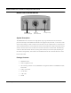
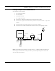
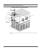
Table Of Contents
- Chapter 1 Introduction
- Features and Benefits
- Equipment Features
- SPEEDLAN K2's Polling Protocol -- How it Works in Star Networks
- SPEEDLAN 9000 Mesh Protocol -- How It Works in Non-Line-of-Sight Networks
- Chapter 2 Installing the SPEEDLAN 9101 & SPEEDLAN 9102 Hardware
- Rooftop and Tower Installations Warning
- Hardware Overview
- Drawings of Outdoor, Remote-Mounted Components
- The SPEEDLAN 9101 (with an Attached Standard Omni)
- The SPEEDLAN 9102 (with an External Antenna)
- Chapter 3 Using the SPEEDLAN 9000 Configurator
- Initial Configuration of the SPEEDLAN 9000
- Overview of the SPEEDLAN 9000 Configurator Main Menu
- Logging on to the SPEEDLAN 9000 Configurator
- Interfaces
- System
- Routing
- Wireless
- DHCP Server
- DHCP Relay
- NAT
- Diagnostics & Troubleshooting
- Administrative Access Pages
- Chapter 4 Using SPEEDView
- What is SPEEDView?
- System Requirements
- Installation Instructions
- Starting SPEEDView
- The Program Instructions
- The Main Tab
- Options Tab
- Admin Tab
- Chapter 5 Basics of IP Addressing
- Basics of IP Addressing
- Glossary for Standard Data Communications
- Glossary for Standard Data Communications
- Software License Agreement

SPEEDLAN 9000 Series Installation and Operation User Guide
2-14 Installing the SPEEDLAN 9101 & SPEEDLAN 9102 Hardware
the unit/router to the wall or concrete by using the concrete or wood mounting screws.
Make sure it is secured.
Step 4. Running and Securing All Cable
The installation kit includes two cables with ready-made connectors to fit your particular installation
needs such as:
• 3’ RF cable
• 10' antenna cable (attaches to antenna one end and to lightning arrestor other end)
• Lightning arrestor (attaches to pigtail and to antenna cable)
a) Attach the 3’ RF cable to the RF port on the SPEEDLAN 9102.
b) Attach the 10' length of cable to the antenna. Next, attach the lightning arrestor to the lower
end of the antenna cable.
c) Attach the other end of lightning arrestor to 3’ RF cable.
d) Run the main length of the specialized Ethernet cable from the router to the indoor junction
box located inside the building.
e) Secure the cable with zip ties or cable clamps during this procedure.
Note: When running the cable through walls or obstructions, make sure that there is ample room
for the connector to pass through without being damaged. Also, do not create extra pressure that
would cause the cable to kink or be stretched or cut (i.e., pulling cable through tight locations).
f) Create a proper weatherproofing seal on all outdoor connections by wrapping it with
electrical tape and sealing it with putty. This is the most crucial step of the installation. If this
procedure is not completed, long-term and complex problems could occur. For more infor-
mation on implementing this procedure, see Weatherproofing Connectors, page 2-15.
g) Next, ground the lightning arrestor. For more information, see Grounding the Lightning
Arrestor, page 2-15.