
User's Manual
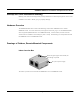
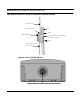
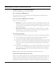
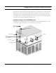
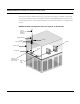
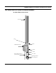
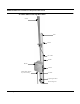
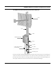
Table Of Contents
- Chapter 1 Introduction
- Features and Benefits
- Equipment Features
- SPEEDLAN K2's Polling Protocol -- How it Works in Star Networks
- SPEEDLAN 9000 Mesh Protocol -- How It Works in Non-Line-of-Sight Networks
- Chapter 2 Installing the SPEEDLAN 9101 & SPEEDLAN 9102 Hardware
- Rooftop and Tower Installations Warning
- Hardware Overview
- Drawings of Outdoor, Remote-Mounted Components
- The SPEEDLAN 9101 (with an Attached Standard Omni)
- The SPEEDLAN 9102 (with an External Antenna)
- Chapter 3 Using the SPEEDLAN 9000 Configurator
- Initial Configuration of the SPEEDLAN 9000
- Overview of the SPEEDLAN 9000 Configurator Main Menu
- Logging on to the SPEEDLAN 9000 Configurator
- Interfaces
- System
- Routing
- Wireless
- DHCP Server
- DHCP Relay
- NAT
- Diagnostics & Troubleshooting
- Administrative Access Pages
- Chapter 4 Using SPEEDView
- What is SPEEDView?
- System Requirements
- Installation Instructions
- Starting SPEEDView
- The Program Instructions
- The Main Tab
- Options Tab
- Admin Tab
- Chapter 5 Basics of IP Addressing
- Basics of IP Addressing
- Glossary for Standard Data Communications
- Glossary for Standard Data Communications
- Software License Agreement

SPEEDLAN 9000 Series Installation and Operation User Guide
Installing the SPEEDLAN 9101 & SPEEDLAN 9102 Hardware 2-5
Installation Steps for the SPEEDLAN 9101
To install your SPEEDLAN 9101, follow the steps below:
Step 1: Mounting the SPEEDLAN 9101
This unit/router will have an omni attached via an RF cable assembly. No additional steps are
needed for this step. Go to Step 2.
Step 2: Mounting the SPEEDLAN 9101 on the Pole
Select one of the two options below:
• Pole Mount: On a pole mount, position the router 5 to 10 feet below the antenna. Then,
attach the router to the mounting pole using the two V-bolted clamps, one on top of the
router and the other on the bottom of the router. Make sure you tighten the screws on the
back of the pole mount.
• Wall or Concrete Mount: On a side building mount, position the router 5 to 10 feet
below the antenna. Then, attach the router to the wall or concrete using the concrete or
wood mounting screws. Make sure the router is secured.
Step 3: Running the Cabling
1 Run CAT5 cable (from bottom of router) down to junction box located inside the building.
2 Secure grounding wire by running this wire to a suitable "earth" ground and fasten it
securely in place. See the installation diagram following these directions.
3 Connect the Junction Box to the Power Supply by connecting the power cord of AC-DC Vdc
adapter to 110 or 220 Vac power outlet (the input voltage of this universal adapter can vary
from 100 to 240 Vac). Connect the DC output of the adapter to DC jack on the indoor
junction box.
4 Connect the wireless SPEEDLAN 9101 to the customer's Ethernet LAN or PC by connecting
the RJ-45 plug on a standard Ethernet CAT5 cable to the white RJ-45 port connector on
indoor junction box. Connect the other end of the Ethernet CAT5 cable to your Ethernet
hub, switch or unit/router.
Note: The lightning arrestor and RF cable assembly is enclosed inside the router.
Important Note: Waterproofing the Connectors!
Make sure you waterproof all the connectors, as follows: Apply two layers of electrical tape to the
connector, and leave approximately 3 inches of cable exposed on either side of the connector. An
alternative is to begin at the lowest point, so the tape overlaps from bottom to top creating a
shingled effect. (This creates an effective barrier against runoff.) Apply this "shingle effect" to each