
User's Manual
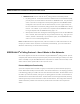
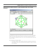
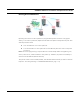
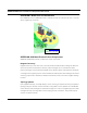
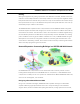
Table Of Contents
- Chapter 1 Introduction
- Features and Benefits
- Equipment Features
- SPEEDLAN K2's Polling Protocol -- How it Works in Star Networks
- SPEEDLAN 9000 Mesh Protocol -- How It Works in Non-Line-of-Sight Networks
- Chapter 2 Installing the SPEEDLAN 9101 & SPEEDLAN 9102 Hardware
- Rooftop and Tower Installations Warning
- Hardware Overview
- Drawings of Outdoor, Remote-Mounted Components
- The SPEEDLAN 9101 (with an Attached Standard Omni)
- The SPEEDLAN 9102 (with an External Antenna)
- Chapter 3 Using the SPEEDLAN 9000 Configurator
- Initial Configuration of the SPEEDLAN 9000
- Overview of the SPEEDLAN 9000 Configurator Main Menu
- Logging on to the SPEEDLAN 9000 Configurator
- Interfaces
- System
- Routing
- Wireless
- DHCP Server
- DHCP Relay
- NAT
- Diagnostics & Troubleshooting
- Administrative Access Pages
- Chapter 4 Using SPEEDView
- What is SPEEDView?
- System Requirements
- Installation Instructions
- Starting SPEEDView
- The Program Instructions
- The Main Tab
- Options Tab
- Admin Tab
- Chapter 5 Basics of IP Addressing
- Basics of IP Addressing
- Glossary for Standard Data Communications
- Glossary for Standard Data Communications
- Software License Agreement

SPEEDLAN 9000 Series Installation and Operation User Guide
Introduction 1-13
and several SPEEDLAN 9000 units/routers. Connecting base stations to a high-speed backhaul
provides the necessary bandwidth for network expansion and eliminates bandwidth bottlenecks.
Broadband Backbone Links
The two-high speed microwave links provide full-duplex 100Mb/s backbone links to other areas of
the MAN. These 100Mb/s microwave backbone links provide the necessary bandwidth for network
expansion and eliminate bandwidth bottlenecks. Service providers can save money because they will
no longer have to depend on backhaul support from the telecommunications infrastructures.
The three polling base stations create a broadband wireless MAN, while operating independently
from the telecommunications infrastructure. The three base stations have been installed on three
non-overlapping 2.4 GHz channels, providing 11 Mb/s of connectivity to three sectors of the
network (total of 100Mbps). This effectively gives the ISP a 33 Mb/s base station from which to
increase the network penetration and user density. Each remote base station uses directional
antennas to achieve maximum distance and to prevent interference from the other base stations.
These sectorized base stations then connect to SPEEDLAN 9000s, which are located in NLOS pico
cells throughout the sectors (represented as yellow, circular cells in the diagram above). As a
provider's network grows, connections may be expanded incrementally to create entire wireless
metropolitan area networks, up to 25 miles from the base station.
Building a SPEEDLAN 9000 Network
The SPEEDLAN 9000 series can be spread throughout the MAN to make it possible to deliver high-
speed Internet services to a wide variety of buildings: enterprises, schools, hospitals, to companies
that relocate or need to expand their network. Previously, the ISP could not reach these buildings
blocked by LOS limitations, such as hills and trees. The SPEEDLAN 9000 series contains the Mesh
protocol to go around obstructed buildings. These specialized networks are referred to a NLOS
pico-cells. (In the previous diagram, these NLOS pico cells are represented as yellow, circular cells.)
NLOS Pico Cells
Each unit/router in a NLOS pico cell is capable of routing data to its destination. Traffic can be
routed around buildings, trees, and other obstructions because this NLOS unit/router simply locates
the next closest unit/router within LOS.