
User's Manual
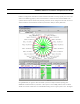
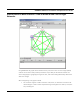
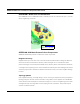
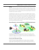
Table Of Contents
- Chapter 1 Introduction
- Features and Benefits
- Equipment Features
- SPEEDLAN K2's Polling Protocol -- How it Works in Star Networks
- SPEEDLAN 9000 Mesh Protocol -- How It Works in Non-Line-of-Sight Networks
- Chapter 2 Installing the SPEEDLAN 9101 & SPEEDLAN 9102 Hardware
- Rooftop and Tower Installations Warning
- Hardware Overview
- Drawings of Outdoor, Remote-Mounted Components
- The SPEEDLAN 9101 (with an Attached Standard Omni)
- The SPEEDLAN 9102 (with an External Antenna)
- Chapter 3 Using the SPEEDLAN 9000 Configurator
- Initial Configuration of the SPEEDLAN 9000
- Overview of the SPEEDLAN 9000 Configurator Main Menu
- Logging on to the SPEEDLAN 9000 Configurator
- Interfaces
- System
- Routing
- Wireless
- DHCP Server
- DHCP Relay
- NAT
- Diagnostics & Troubleshooting
- Administrative Access Pages
- Chapter 4 Using SPEEDView
- What is SPEEDView?
- System Requirements
- Installation Instructions
- Starting SPEEDView
- The Program Instructions
- The Main Tab
- Options Tab
- Admin Tab
- Chapter 5 Basics of IP Addressing
- Basics of IP Addressing
- Glossary for Standard Data Communications
- Glossary for Standard Data Communications
- Software License Agreement

SPEEDLAN 9000 Series Installation and Operation User Guide
Introduction 1-9
• You will note that the Trace button is selected, which traces the data flow between the
selected pairs or links. This example displays a trace route (hint: look for black beads)
between the selected nodes. You will see the links chosen by the routing algorithm in order
to send data from the source node to the destination node.
• SPEEDView also displays the broken links, and you can also use the "Block" feature to test a
"mock" link that is disconnected. The broken (or disconnected) link will appear as a red,
dashed line. This link appears when there is no signal strength between nodes. This exam-
ple displays a broken mock link between the node pair.
• SPEEDView also displays the data flow (upstream, downstream and combined total) for the
selected nodes on the network in the lower window which is referred to as the Statistics win-
dow. SPEEDView can also be used to perform bandwidth, link and ping tests. For more
information about SPEEDView, see the separate document titled, "SPEEDView Quick Start
Guide."
So, how do mesh topology solutions reach buildings obstructed from line-of-
sight issues?
Based on the routing protocol called Topology Based Reverse Path Forwarding (TBPPF), SPEEDLAN’s
mesh technology provides each unit/router the unique ability to learn multiple network paths that
traffic can follow. Using specialized routing algorithms, its network radios are updated without
degrading bandwidth or efficiency, as with other full-topology protocols.
The rest of this section explains each unique component of a mesh topology solution: how it routes
around obstacles, its NLOS pico cell architecture, Mesh protocol's core components, and how it
expands or integrates with the network.