
User's Manual
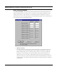
Table Of Contents
- Chapter 1 Introduction
- Product Description and Contents
- Product Features
- Chapter 2 Quick Start
- Rooftop and Tower Installations Warning
- Installation Steps
- Installation Diagrams
- Chapter 3 Hardware
- Drawings of Components
- SPEEDLAN 8500 ODU Hardware
- Antenna
- Restoring Factory Default Settings on the SPEEDLAN 8500 IDU
- Upgrading the Firmware
- Chapter 4 Overview of Configurator
- Installation and Setup
- Toolbar and Menus
- Chapter 5 Configuring SPEEDLAN
- General Setup
- Interface & Advanced Interface Setup
- The Setup Buttons
- Chapter 6 Bridging Setup
- IDU Setup
- Chapter 7 Setting Up the IP Addresses (IP Host Setup)
- Part I - Quick Overview of IP Addressing
- Part II - Setting Up the IP Address
- Part III - Setting Up NAT
- Chapter 8 IP-Router Setup
- IP Routing Setup
- Chapter 9 SNMP Setup
- SNMP Setup
- Chapter 10 System Access Setup
- System Access Setup
- Chapter 11 SNMP Monitoring
- Remote Statistics
- Interface Monitor
- Ethernet-like Interface Monitor
- SectorPRC Station Entries
- 11Mb RF Interface
- SNMP Monitor
- IP Monitor
- IP/TCP/UDP Monitor
- ICMP Monitor
- Chapter 12 Tables
- System Information
- IDU Learn Table
- IP ARP Table
- IP Route Table
- IP/TCP Connection Table
- IP/UDP Listener Table
- Local IP-Address Table
- Chapter 13 Analyzing Wireless Equipment
- Select Another Device
- Analysis Polling Interval
- Wireless Link Test
- Antenna Alignment
- Glossary for Standard Data Communications
- Glossary for Standard Data Communications
- Appendixes
- Appendix A Protocols & Ethernet Addresses
- Common Ethernet Protocols
- Common Ethernet Vendor Addresses
- Common Ethernet Multicast Addresses
- Common Ethernet Broadcast Addresses
- Appendix B Startup LED Patterns
- Startup LED Patterns

SPEEDLAN 8500 Series Installation and Operation User Guide
Setting Up the IP Addresses (IP Host Setup) 7-5
• Class D
• Range is 224.0.0.0 to 239.255.255.255
• Used for multicast packets (i.e., host sends out router discovery packets to learn all of
the routers on the network)
• Class E
• Range is 240.0.0.0 to 255.255.255.255
• Reserved for future use
Note: Class D & E should NOT be assigned to net assignment of IP addresses. In addition,
the first octet, 127, is reserved. In each network definition, the first node number (i.e.,
"0") is used to define the network, as well as the last number (i.e., "255"). The last num-
ber is known as the broadcast address.
Public IP addresses can be obtained from the following address:
Network Solutions
InterNIC Registration Services
505 Huntmar Park Drive
Herndon, VA 22070
hostmaster@internic.net
Note: Non-public addresses can include a network address assigned from the network
administrator or from the IP provider. Also, there is one network in each class that is
defined for private use, allowing the creation of internal networks. These addresses are
Class A: 10.0.0.0, Class B: 172.10.0.0, and Class C: 192.168.0.0.
Subnetting a Network
The increasing number of hosts and networks make impractical address blocks that are not smaller
than 245. In order keep the IP address small, so routers can manage them without changing the
whole protocol, a smaller network definition is created. This is called a subnet. Subnets are intended
to:
• Reduce network traffic
• Optimize performance
• Simplify management
• Create more effective and efficient addresses for large geographic distances