
User's Manual

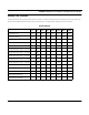
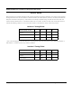
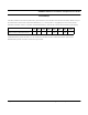

Table Of Contents
- Chapter 1 Introduction
- Product Description and Contents
- Product Features
- Chapter 2 Quick Start
- Rooftop and Tower Installations Warning
- Installation Steps
- Installation Diagrams
- Chapter 3 Hardware
- Drawings of Components
- SPEEDLAN 8500 ODU Hardware
- Antenna
- Restoring Factory Default Settings on the SPEEDLAN 8500 IDU
- Upgrading the Firmware
- Chapter 4 Overview of Configurator
- Installation and Setup
- Toolbar and Menus
- Chapter 5 Configuring SPEEDLAN
- General Setup
- Interface & Advanced Interface Setup
- The Setup Buttons
- Chapter 6 Bridging Setup
- IDU Setup
- Chapter 7 Setting Up the IP Addresses (IP Host Setup)
- Part I - Quick Overview of IP Addressing
- Part II - Setting Up the IP Address
- Part III - Setting Up NAT
- Chapter 8 IP-Router Setup
- IP Routing Setup
- Chapter 9 SNMP Setup
- SNMP Setup
- Chapter 10 System Access Setup
- System Access Setup
- Chapter 11 SNMP Monitoring
- Remote Statistics
- Interface Monitor
- Ethernet-like Interface Monitor
- SectorPRC Station Entries
- 11Mb RF Interface
- SNMP Monitor
- IP Monitor
- IP/TCP/UDP Monitor
- ICMP Monitor
- Chapter 12 Tables
- System Information
- IDU Learn Table
- IP ARP Table
- IP Route Table
- IP/TCP Connection Table
- IP/UDP Listener Table
- Local IP-Address Table
- Chapter 13 Analyzing Wireless Equipment
- Select Another Device
- Analysis Polling Interval
- Wireless Link Test
- Antenna Alignment
- Glossary for Standard Data Communications
- Glossary for Standard Data Communications
- Appendixes
- Appendix A Protocols & Ethernet Addresses
- Common Ethernet Protocols
- Common Ethernet Vendor Addresses
- Common Ethernet Multicast Addresses
- Common Ethernet Broadcast Addresses
- Appendix B Startup LED Patterns
- Startup LED Patterns

SPEEDLAN 8500 Series Installation and Operation User Guide
Appendix B Startup LED Patterns Appendix B-3
Interface Startup
After initial startup is complete and LEDs are de-powered, the IDU kernel will then attempt to auto configure each interface
starting with the first one. As each interface is started and tested, the 3 LEDs (Receive, Transmit, and Error) associated with
that particular interface will power-up. If the interface successfully completes testing, the LEDs will shut off and the next
interface will be probed. If there is a hardware problem with an interface, the IDU will either halt with the LEDs left on to
indicate the offending interface or if it has one good interface it will attempt to startup and forward packets.
Interface 1 Testing/Failed*
* This is also the display you see when there are no ports present. This is because the IDU cannot distinguish between a
bad Interface 1 and does not have any interfaces installed.
Interface 2 Testing/Failed
Interface (Port) Number1234
Receive ON
Transmit ON
Error/Collision ON
Interface (Port) Number1234
Receive ON
Transmit ON
Error/Collision ON