
User's Manual

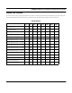
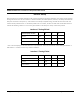


Table Of Contents
- Chapter 1 Introduction
- Product Description and Contents
- Product Features
- Chapter 2 Quick Start
- Rooftop and Tower Installations Warning
- Installation Steps
- Installation Diagrams
- Chapter 3 Hardware
- Drawings of Components
- SPEEDLAN 8500 ODU Hardware
- Antenna
- Restoring Factory Default Settings on the SPEEDLAN 8500 IDU
- Upgrading the Firmware
- Chapter 4 Overview of Configurator
- Installation and Setup
- Toolbar and Menus
- Chapter 5 Configuring SPEEDLAN
- General Setup
- Interface & Advanced Interface Setup
- The Setup Buttons
- Chapter 6 Bridging Setup
- IDU Setup
- Chapter 7 Setting Up the IP Addresses (IP Host Setup)
- Part I - Quick Overview of IP Addressing
- Part II - Setting Up the IP Address
- Part III - Setting Up NAT
- Chapter 8 IP-Router Setup
- IP Routing Setup
- Chapter 9 SNMP Setup
- SNMP Setup
- Chapter 10 System Access Setup
- System Access Setup
- Chapter 11 SNMP Monitoring
- Remote Statistics
- Interface Monitor
- Ethernet-like Interface Monitor
- SectorPRC Station Entries
- 11Mb RF Interface
- SNMP Monitor
- IP Monitor
- IP/TCP/UDP Monitor
- ICMP Monitor
- Chapter 12 Tables
- System Information
- IDU Learn Table
- IP ARP Table
- IP Route Table
- IP/TCP Connection Table
- IP/UDP Listener Table
- Local IP-Address Table
- Chapter 13 Analyzing Wireless Equipment
- Select Another Device
- Analysis Polling Interval
- Wireless Link Test
- Antenna Alignment
- Glossary for Standard Data Communications
- Glossary for Standard Data Communications
- Appendixes
- Appendix A Protocols & Ethernet Addresses
- Common Ethernet Protocols
- Common Ethernet Vendor Addresses
- Common Ethernet Multicast Addresses
- Common Ethernet Broadcast Addresses
- Appendix B Startup LED Patterns
- Startup LED Patterns

SPEEDLAN 8500 Series Installation and Operation User Guide
AppendixB-2 Appendix B Startup LED Patterns
Startup LED Patterns
On startup the IDU will go through several start up tests. If any of the tests fail, the IDU will display a particular pattern for
the Forwarding Rate% (located on the front panel of the IDU). The table below explains some test scenarios:
Initial Startup
1% 5% 10% 20% 40% 60% 80% 100%
Initial Power On ON ON ON ON ON ON ON ON
Boot ROM Starting ON ON ON ON
Running from BOOT ROM ONONON ON
Bad Temperature Chip Low ON ON
Bad Temperature High ON ON
Grade Mismatch: Flash = Grade1 ON
Grade Mismatch: Flash = Grade2 ON ON
Grade Mismatch: Flash = Grade3 ON ON
Grade Mismatch: Flash = Grade4 ON ON ON
Grade Mismatch: Flash = Grade5 ON ON
Grade Mismatch: Flash = Grade6 ON ON ON
Grade Mismatch: Flash = Grade7 ON ON ON
Grade Mismatch: Flash = Grade8 ON ON ON ON
Bad Serial Number Key ON ON
Initial Startup Complete