
User's Manual
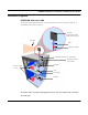
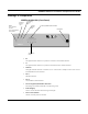
Table Of Contents
- Chapter 1 Introduction
- Product Description and Contents
- Product Features
- Chapter 2 Quick Start
- Rooftop and Tower Installations Warning
- Installation Steps
- Installation Diagrams
- Chapter 3 Hardware
- Drawings of Components
- SPEEDLAN 8500 ODU Hardware
- Antenna
- Restoring Factory Default Settings on the SPEEDLAN 8500 IDU
- Upgrading the Firmware
- Chapter 4 Overview of Configurator
- Installation and Setup
- Toolbar and Menus
- Chapter 5 Configuring SPEEDLAN
- General Setup
- Interface & Advanced Interface Setup
- The Setup Buttons
- Chapter 6 Bridging Setup
- IDU Setup
- Chapter 7 Setting Up the IP Addresses (IP Host Setup)
- Part I - Quick Overview of IP Addressing
- Part II - Setting Up the IP Address
- Part III - Setting Up NAT
- Chapter 8 IP-Router Setup
- IP Routing Setup
- Chapter 9 SNMP Setup
- SNMP Setup
- Chapter 10 System Access Setup
- System Access Setup
- Chapter 11 SNMP Monitoring
- Remote Statistics
- Interface Monitor
- Ethernet-like Interface Monitor
- SectorPRC Station Entries
- 11Mb RF Interface
- SNMP Monitor
- IP Monitor
- IP/TCP/UDP Monitor
- ICMP Monitor
- Chapter 12 Tables
- System Information
- IDU Learn Table
- IP ARP Table
- IP Route Table
- IP/TCP Connection Table
- IP/UDP Listener Table
- Local IP-Address Table
- Chapter 13 Analyzing Wireless Equipment
- Select Another Device
- Analysis Polling Interval
- Wireless Link Test
- Antenna Alignment
- Glossary for Standard Data Communications
- Glossary for Standard Data Communications
- Appendixes
- Appendix A Protocols & Ethernet Addresses
- Common Ethernet Protocols
- Common Ethernet Vendor Addresses
- Common Ethernet Multicast Addresses
- Common Ethernet Broadcast Addresses
- Appendix B Startup LED Patterns
- Startup LED Patterns

SPEEDLAN 8500 Series Installation and Operation User Guide
Quick Start 2-5
d) Mount the DC injector indoors, as shown in the installation diagram at the end of this sec-
tion. Attach the DC injector to a flat surface using screws or bolts through the mounting
flanges. Do not over set the power supply. The DC injector will inject the DC power to oper-
ate to amplify into the transmission line, which allows the coaxial cable to carry RF and DC
power to the ODU mounted on the mast or tower. Make sure that the DC injector is
grounded as well.
Step 7. Connect the Wireless IDU to any Available Outlet of the Ethernet LAN
a) Connect the RJ-45 connector on a standard Ethernet cable to the RJ-45 port on the back
panel of the IDU.
b) Connect the other end of the Ethernet cable to your Ethernet hub, switch or router.
Step 8. Repeat If Needed
Repeat Steps 1-6 for all of the SPEEDLAN 8500 IDUs that will be communicating with this one.
Step 9. Check Functionality Using the LED Indicators.
When the installation is complete, activate the SPEEDLAN IDU. The radio will automatically transmit
a “hello” packet to the other IDU(s) to initiate communication. When a remote IDU is located, the
IDU will synchronize themselves with each other once communication is established. Then, the IDU
will start forwarding data packets to the wireless LAN that is connected to them. When the IDUs are
“handshaking” correctly, you will see the receive and transmit lights blink on and off as they
communicate.
As the IDUs forward data back and forth to one another, you may occasionally see a collision light
on the display panel. This is a normal aspect of networking. A solid collision light displayed on the
front panel indicates that the particular interface is not able to detect a link.
If you think the IDU is not configured or operating properly, try troubleshooting the problem by
seeing Appendix B Startup LED Patterns, page Appendix B-1.