
User's Manual
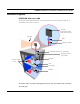
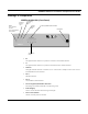
Table Of Contents
- Chapter 1 Introduction
- Product Description and Contents
- Product Features
- Chapter 2 Quick Start
- Rooftop and Tower Installations Warning
- Installation Steps
- Installation Diagrams
- Chapter 3 Hardware
- Drawings of Components
- SPEEDLAN 8500 ODU Hardware
- Antenna
- Restoring Factory Default Settings on the SPEEDLAN 8500 IDU
- Upgrading the Firmware
- Chapter 4 Overview of Configurator
- Installation and Setup
- Toolbar and Menus
- Chapter 5 Configuring SPEEDLAN
- General Setup
- Interface & Advanced Interface Setup
- The Setup Buttons
- Chapter 6 Bridging Setup
- IDU Setup
- Chapter 7 Setting Up the IP Addresses (IP Host Setup)
- Part I - Quick Overview of IP Addressing
- Part II - Setting Up the IP Address
- Part III - Setting Up NAT
- Chapter 8 IP-Router Setup
- IP Routing Setup
- Chapter 9 SNMP Setup
- SNMP Setup
- Chapter 10 System Access Setup
- System Access Setup
- Chapter 11 SNMP Monitoring
- Remote Statistics
- Interface Monitor
- Ethernet-like Interface Monitor
- SectorPRC Station Entries
- 11Mb RF Interface
- SNMP Monitor
- IP Monitor
- IP/TCP/UDP Monitor
- ICMP Monitor
- Chapter 12 Tables
- System Information
- IDU Learn Table
- IP ARP Table
- IP Route Table
- IP/TCP Connection Table
- IP/UDP Listener Table
- Local IP-Address Table
- Chapter 13 Analyzing Wireless Equipment
- Select Another Device
- Analysis Polling Interval
- Wireless Link Test
- Antenna Alignment
- Glossary for Standard Data Communications
- Glossary for Standard Data Communications
- Appendixes
- Appendix A Protocols & Ethernet Addresses
- Common Ethernet Protocols
- Common Ethernet Vendor Addresses
- Common Ethernet Multicast Addresses
- Common Ethernet Broadcast Addresses
- Appendix B Startup LED Patterns
- Startup LED Patterns

SPEEDLAN 8500 Series Installation and Operation User Guide
Quick Start 2-3
SPEEDLAN 8500 Instructions
To install the SPEEDLAN 8500, do the following:
Step 1. Line of Sight
Before installing the antenna and ODU, make sure a clear line of sight exists. Line of sight can be
defined as each antenna having a clear transmission path between the two antennas with no
physical obstructions (e.g., trees, buildings, hills, etc.). Be sure to look level with the center of origin
of the transmission (the middle of the antenna). Do the same from the remote location. Any
disruption of the signal path due to trees, buildings or any other obstructions may cause the link to
function improperly. If you see any such obstruction between the two antennas, move one or both
antennas to a different location on the building, or install on antenna mast or tower to gain height.
Step 2. Mount the Antenna
a) On a side building mount, as in the diagram at the end of this section, position the bracket
so there will be at least three feet (one meter) above the roof line of the building where the
pole is attached; this leaves room for the antenna and reduces signal loss from building
reflection.
b) Allow for as much space between the wall brackets as possible while still maintaining the
antenna height that is necessary. For extended poles, additional wall brackets may be nec-
essary.
c) Assemble the antenna and mount it to the pole using the U-bolt hardware included in the
installation kit. Make sure all bolts and screws are fastened tightly.
d) Fasten the pole to the brackets. Position the antenna, point it in the appropriate direction,
and tighten the screws.
Step 3. Mount the ODU to the mast or tower
a) Mount the ODU case to the mast or tower using the U-bolt mounting hardware included in
the installation kit. The RF connectors would not face downward but sideward. For more
details, see Installation Diagrams, page 2-6.
b) Tighten bolts with an open-end wrench, but do not overtighten them.
c) Make sure you mount the ODU as far away as possible from the other radio transmitters,
regardless of their frequency range. Make sure there are no obstructions in front of the
antenna.
d) Waterproof the connectors using cable sealant putty provided in the installation kit.