
Manual


2
I. Important Safety Information –
Read All
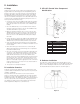
Filter Anatomy
!
CAUTION: Read and follow the information in this manual
to minimize the risk of electric shock or personal injury.
Important: If you are unsure about installing your Watts water
filter, contact a Watts representative or consult a professional
plumber.
A. READ Instructions Before Using
• After reading these instructions completely, obtain all the
materials and tools needed for installation.
NOTE: Failure to install the system correctly voids the warranty.
• Perform installation according to state, province and local
plumbing codes.
Use only lead-free solder and flux for sweat-solder
connections, as required by state, province and federal
codes.
• Handle all components of the system with care. Do not drop,
drag or turn components upside down.
• Be sure the oor under the water lter system is clean, level
and strong enough to support the unit.
• The system uses 24 volt-60Hz electrical power. Always use
the transformer supplied.
Plug transformer into an indoor 120 VAC, grounded outlet.
Properly ground the system to conform with all codes and
ordinances.
• Install the system in a protected area. Be sure electric outlet
and transformer do not come in contact with water. See
Installation Considerations, in the installation section of the
manual.
Do not attempt to treat water over 110°F (43°C) with the
system. Always connect the system to the main water
supply pipe before the water heater.
Do not expose the system to freezing temperatures. Wa-
ter freezing in the system causes equipment damage.
Do not install in direct sunlight. Ultraviolet rays from the
sun may cause damage.
• Minimum inlet water pressure is 30 psi. Maximum inlet water
pressure is 80 psi. Use a pressure reducing valve if neces-
sary.
!
CAUTION:
• Do not use with water that is microbiologically unsafe or of
unknown quality.
• Test the water periodically to verify that the system is per-
forming satisfactorily.
• Discard small parts remaining after the installation.
Figure 1
ITEM DESCRIPTION
1 Control Valve
2 Bypass Valve
3 Mineral Tank
4 Distributor Tube
5 Filter Media
6 Faceplate/Control
7 Gravel Underbedding
1
2
3
4
5
6
7