
User Manual


5
Setup
Unpack and check the system components for damage or missing
parts.
Make sure that the bypass valve and plumbing yoke are properly
connected to each other and to the control valve with the mounting
clips. Make certain that the drain line flow control fitting is installed
properly on the drain port of the control valve. Systems that are 13”
in diameter and larger are not loaded with media. These systems
must be loaded with media before placing into service. To load a
system follow the below steps.
1. Cap the top open end of the distributor tube with tape and plas-
tic sheeting to keep foreign debris from entering the distributor
tube. This cap must be secure and not come off during media
loading.
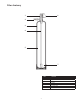
2. Place the distributor tube, screen end down, into the mineral
tank and center it in the bottom. The top of the distributor tube
should be flush with the top of the tank.
3. Make sure the plastic and tape cap is secure to the top of the
distributor tube, place a funnel on the top of the tank and load
first the gravel then the filter media into the tank. The cap must
not come off of the distributor tube during the loading of the
media.
4. Remove the plastic cap from the distributor tube. DO NOT PULL
UP ON THE DISTRIBUTOR TUBE when removing the cap. The
distributor tube top must remain flush with the top of the tank.
5. Clean any media from the threads and top of the mineral tank.
6. Lubricate the O-rings on the bottom of the control valve (dis-
tributor pilot O-ring and top of tank O-ring). Use non-petroleum
based silicone lubricant only.
7. Place the control valve on top of the tank. When doing this step,
seat the top of the distributor tube inside the centered O-ring
sealed port on the bottom of the valve first then press the valve
down until the tank threads come in contact with the valve
threads. This ensures that the distributor tube is properly seated
into the bottom of the control valve. Thread the valve on to the
tank clockwise. Be careful not to cross thread the valve or over
tighten it. A hand tight snug fit is appropriate for the control valve
torque. A wrench is not necessary. Do not use thread sealant or
PTFE tape on the valve base threads.
8. The system is now ready for installation.
Installation Considerations
Consider the following points when determining where to install
the filter:
• Place the system as close as possible to a sewer drain.
• Do not install the lter where it would block access to the water
heater, or access to the main water shutoff, water meter, or electri-
cal panels.
• Install the lter in a place where water damage is least likely to oc-
cur if a leak develops.
• A 120VAC electrical outlet is needed to plug in the transformer.
• Always connect the system to the main water supply pipe before
the water heater.
• Install the system where it will not be subject to temperatures
outside of the limits stated in the Specification section or to direct
sunlight.
• Make sure the installation surface is smooth, level, and sturdy
enough to support the weight of the wetted system.