
Installation Instructions

Page 4
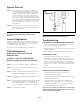
System Module Mounting
Inlet and Outlet Tube Connection
- Filtration System
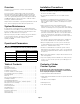
Step 1 - Mount the system to
one side of the cabinet
allowing 2" of clearance
below the lter for
easy lter removal and
replacement.
Step 2 - Using the mounting
bracket, mark with a
pencil the holes for the
mounting screws on the
wall surface.
Step 3 - Using a 1/8" drill bit,
drill pilot holes for the
mounting screws. Insert
mounting screws into the
wall with a screwdriver leaving approximately 3/8"
of each mounting screw exposed and hang system
head on the mounting holes of the bracket.
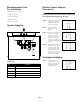
Step 1 - Determine two different
lengths of 3/8" tubing
needed to connect the
system head inlet and
outlet to the kitchen
faucet adapter (reference
image for inlet and for
outlet locations and
directions on the right for cutting and installing the
tubing). Be sure to allow enough tubing to prevent
kinking in the line.
Step 2 - Wet one end of the 3/8"
plastic tubing with water
and push it into the inlet
side of the system head
approximately 5/8" until it
stops. Connect the other
end of the tubing to the
inlet side of the kitchen faucet adapter. Refer to Quick-
Connect instructions on the right for more detail.
Step 3 - Repeat same process with outlet side.
Reference image for inlet and outlet locations.
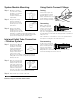
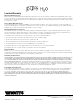
NOTICE
Cut the tube square. It is
essential that the outside
diameter be free of score
marks, and that burrs and
sharp edges be removed
before inserting into tting.
Using Quick-Connect Fittings
Cutting
Make certain to push
the tubing completely
into the connector until
it comes into contact
with the internal tubing
stop. The collet (gripper) has stainless steel teeth which hold
the tube rmly in position while the O-ring provides a permanent
leak proof seal.
Pull on the tube to check that it is secure. The system must be
tested prior to leaving the site and/or before use.
To disconnect, ensure the
system is depressurized
before removing the tube.
Push in collet squarely
against the face of the
tting. With the collet held in this position, the tube can be
removed. The tting can then be reused.
Connecting
Disconnecting