
Specification
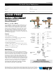

Materials
Springs: Stainless Steel
Bonnet: Celcon
®
VentDisc: SiliconeRubber
DiscHolderFloat: Polypropylene
CheckValveDisc: SiliconeRubber
CheckValveSeat: Noryl
®
Plastic
Body: LeadFree*CastCopperSiliconAlloy
Pressure - Temperature
TemperatureRange:33°Fto140°(0.5°Cto60°C)
MaximumWorkingPressure:150psi(10.3bar)
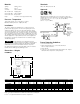
Installations
This valve is designed for installation in a continuous pressure
potable water supply system 12" above the highest point of the
downstream piping. The valve must be installed with the supply
connectedtothebottomandinaverticalposition.Allowadequate
space for periodic inspection, servicing or testing. The valve should
notbeinstalledinanareawherefreezingorspillagewillcausedam-
age.Adequatedrainage/freezeprotectionmustbeprovidedincold
weatherapplications.1.5psi(10kPa)mustbeexertedagainstthe
floatspringtosealthefloatandairinlet.Donotundersizesupply
and discharge piping.
Vacuumbreakersarenotdesigned,testedor
approved to protect against backpressure backflow or water hammer
shock.Forprotectionagainstbackpressurebackflow,installWatts
LF009ReducedPressureZoneBackflowPreventer.Forprotec-
tionagainstwaterhammershockinstallaWattsSeriesLF15Water
HammerArrestorutilizinggoodplumbingpractice.
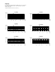
Dimensions – Weights
LF800M4QT
Standards
ANSI,USCManualSection10
Approvals
ApprovedbythefoundationforCross-ConnectionControland
HydraulicResearchattheUniversityofSouthernCalifornia,Manual
Section 10.
1
⁄2",
3
⁄4", 1
1
⁄4", 1
1
⁄2", 2" (15, 20, 32, 40, 50mm)
1" (25mm) pending
CSA
1
⁄2" – 2" (15 - 50mm)
D
C
E
A
G
B
Freeze Protection Guidelines
1.Closemainshutoffvalve.
2. Open upstream drain, test cocks and isolation ball
valvestodepressurizeline.
3.Purgewithair.
4. Leave test cocks and isolation ball valve handles in 45° angle to
drain ball valves and prevent casting damage.
45°
Union
OutletDrain
Valve
Flow
InletDrain
MainShutoffValve
12" (300mm)
Minimum
clearance
above the
highest point
of down-
stream
piping.
1020
Noryl
®
isaregisteredtrademarkofSABICInnovativePlasticsHoldingBV.
Celcon
®
isaregisteredtrademarkofCelaneseCorporation.
MODEL SIZE (DN) DIMENSIONS WEIGHT
A B C D E G
in. mm in. mm in. mm in. mm in. mm in. mm in. mm lbs. kg.
LF800M4QT
1
⁄2
15 6
1
⁄8
156 6
1
⁄4
159 2
9
⁄16
65 3
11
⁄16
94 3
7
⁄8
98 2
1
⁄4
57 4 1.8
LF800M4QT
3
⁄4
20 6
1
⁄2
165 6
1
⁄2
165 2
9
⁄16
65 3
15
⁄16
100 4
1
⁄8
105 2
1
⁄4
57 4 1.8
LF800M4QT 1 25 7
1
⁄2
191 7
1
⁄2
191 2
3
⁄4
70 4
3
⁄4
121 4
7
⁄8
124 3
7
⁄16
87 6 2.7
LF800M4QT 1
1
⁄4
32 8
7
⁄8
225 9 229 3
1
⁄4
83 5
3
⁄4
146 6
1
⁄8
156 5 127 11 5.0
LF800M4QT 1
1
⁄2
40 9
1
⁄4
235 9
1
⁄2
241 3
1
⁄4
83 6
1
⁄4
159 6
3
⁄8
162 5 127 14 6.3
LF800M4QT 2 50 10
5
⁄8
270 9
5
⁄8
245 3
1
⁄4
83 6
3
⁄8
162 7 178 5 127 19 8.6
NOTICE