
Instruction Manual

Sizing and Placement
Rule 1 covers multiple fixture branch lines which do not
exceed 20 ft. (6m) in length.
Explanation - Fixture-unit sizing and selection table is used
to select the required PDI unit (water hammer arrestor).
Rule 2 covers multiple fixture branch lines which do exceed
20 ft. (6m) in length.
Explanation - Fixture-unit sizing and selection table is used
to select the required PDI unit (water hammer arrestor). The
sum of the fixture units rating of units X and Y shall be equal
to or greater than the demand of the branches.
X
Up to 20 ft. (6m)
Y
X
Over 20 ft. (6m)
Rule 1
Rule 2
Riser
Typical Branch Line
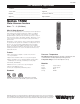
No. 15M2
Water Hammer Arrestor
As shown, it has been established that the preferred location
for the water hammer arrestor is at the end of the branch line
between the last two fixtures served.
The location of the water hammer arrestor shown above applies
to branch lines that do not exceed 20 ft. (6m) in length, from the
start of the horizontal branch line to the last fixture supply on
this branch line. When the branch line exceeds the 20 ft. (6m)
length, an additional water hammer arrestor should be used.
This practice is best defined by two rules which have been
established to cover the placement of water hammer arrestors.
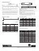
Sizing and Selection Table
Fixture Units Sizing Information
Dimensions - Weight
SIZE (DN) MODEL ORDER CODE
CROSS FIXTURE
UNITS
REF. PDI
STANDARD
in. mm Threaded
1
⁄2" 15 15M2-A 0750140 1-11 A
3
⁄4" 20 15M2-B 0750141 12-32 B
1" 25 15M2-C 0750142 33-60 C
1" 25 15M2-D 0750143 61-113 D
1" 25 15M2-E 0750144 114-154 E
1" 25 15M2-F 0750145 155-330 F
SIZE (DN) DIMENSIONS WEIGHT
A B
in. mm in. mm (lbs) (kgs)
Threaded
1
⁄2" 15M2-A 1
1
⁄8 28.5 5
15
⁄16 150.9 0.5 0.2
3
⁄4" 15M2-B 1
3
⁄8 34.9 8
9
⁄16 218.0 0.9 0.4
1" 15M2-C 1
5
⁄8 41.3 8
13
⁄16 223.5 1.3 0.6
1" 15M2-D 2
1
⁄8 54.0 9
15
⁄16 252.5 2.0 0.9
1" 15M2-E 2
1
⁄8 54.0 12
11
⁄16 322.5 2.3 1.1
1" 15M2-F 2
5
⁄8 66.7 11
5
⁄32 283.5 2.7 1.2
FIXTURE UNITS
TYPE OF SUPPLY PUBLIC PRIVATE
FIXTURE CONTROL TOTAL C.W. H.W. TOTAL C.W. H.W.
Water Closet 1.66 PF Flush Valve 8 8 – 5 5 –
Water Closet 1.66 PF Flush Tank 5 5 – 2.5 2.5 –
Pedestal Urinal 1.06 PF Flush Valve 4 4 – – – –
Stall or Wall Urinal Flush Valve 1.06 PF 4 4 – – – –
Stall or Wall Urinal Flush Tank 1.06 PF 2 2 – – – –
Lavatory Faucet 2 1
1
/2 1
1
/2 1 1 1
Bathtub Faucet 4 2 3 2 1
1
/2 1
1
/2
Shower Head Mixing Valve 4 2 3 2 1 2
Bathroom Group Flush Valve Closet – – – 8 8 3
Bathroom Group Flush Tank Closet – – – 6 6 3
Separate Shower Mixing Valve – – – 2 1 2
Service Sink Faucet 3 3 3 – – –
Laundry Tubs (1-3) Faucet – – – 3 3 3
Combination Fixture Faucet – – – 3 3 3
B
A
ES-15M2 1103 © 2011 Watts
USA: No. Andover, MA • Tel. (978) 688-1811 • Fax: (978) 794-1848 • www.watts.com
Canada: Burlington, ONT. • Tel. (905) 332-4090 • Fax: (905) 332-7068 • www.wattscanada.ca
A Watts Water Technologies Company