
Install Instructions

Watts Model N9/LFN9 and
Model NLF9/LFNLF9
Backflow Preventers
ATTENTION INSTALLER: After installation, please leave this Instruction Sheet for occupant’s information.
IS-N9-NLF9
Watts Model N9/LFN9 and
Model NLF9/LFNLF9
Backflow Preventers
ATTENTION INSTALLER: After installation, please leave this Instruction Sheet for occupant’s information.
IS-N9-NLF9
Installation Instructions
Before installing, flush out pipe lines to remove scale and other foreign
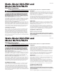
matter. The valves can be installed horizontally or vertically. Install the
valve in the line with the arrow on valve body pointing in the direction
of flow. Model NLF9/LFNLF9 is furnished with inlet thread gasket and
pipe dope or Teflon
®
tape should not be used. However, Teflon
®
tape
is recommended for the pipe threads of Model N9/LFN9. To maintain
the valve discs in a clean operating condition, we strongly recommend a
pipe line strainer be installed in the supply line before the Model N9/LFN9
or Model NLF9/LFNLF9.
Important
These devices are not intended for installation where emergency or tem-
porary water discharge can cause water damage because they are not
designed to be spillage free under all service conditions. For this reason
and for maintenance accessibility, these devices must not be installed
inside a wall or any concealed location.
This device should be installed at the furthermost downstream end of
the supply pipe or fixture where temporary spillage due to critical flow
pressure conditions can be discharged harmlessly. Also, the backflow
preventer will operate most satisfactorily when located as far down-
stream as possible, because any backpressure is minimized.
Application
Watts
3
⁄8" (10mm) Model NLF9/LFNLF9 is recommended for laboratory
faucets and is not suitable for continuous pressure applications. The
Model N9/LFN9 series are recommended for either continuous or inter-
mittent pressure type installations.
Potable water must be protected from backflow of low hazard sub-
stances used in equipment container, sinks and set tubs. In the event
of negative supply pressure such contaminated fluids will not backflow
to the supply source by backsiphonage. For clarification of low hazard
substances consult Local Plumbing Authority or Health Department.
Temperature and Pressure
Maximum Pressure 150psi (10.3 bar).
Maximum Temperature 140°F (60°C).
Annual inspection of all water system safety and control valves is required
and necessary. Regular inspection, testing and cleaning assures maximum life and
proper product function.
Teflon
®
is a registered trademark of the E.I. Dupont de Nemours & Company.
You are required to thoroughly read all installation instructions and
product safety information before beginning the installation of this prod-
uct. FAILURE TO COMPLY WITH PROPER INSTALLATION AND
MAINTENANCE INSTRUCTIONS COULD RESULT IN PRODUCT
FAILURE WHICH CAN CAUSE PROPERTY DAMAGE, PERSONAL
INJURY AND/OR DEATH. Watts is not responsible for damages result-
ing from improper installation and/or maintenance.
Local building or plumbing codes may require modifications to the informa-
tion provided. You are required to consult the local building and plumbing
codes prior to installation. If this information is not consistent with local
building or plumbing codes, the local codes should be followed.
Need for Periodic Inspection/Maintenance: This product must be test-
ed periodically in compliance with local codes, but at least once per year or
more as service conditions warrant. Corrosive water conditions, and/or un-
authorized adjustments or repair could render the product ineffective for the
service intended. Regular checking and cleaning of the product’s internal
components helps assure maximum life and proper product function.
WARNING
!
Installation Instructions
Before installing, flush out pipe lines to remove scale and other foreign
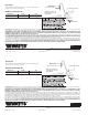
matter. The valves can be installed horizontally or vertically. Install the
valve in the line with the arrow on valve body pointing in the direction
of flow. Model NLF9/LFNLF9 is furnished with inlet thread gasket and
pipe dope or Teflon
®
tape should not be used. However, Teflon
®
tape
is recommended for the pipe threads of Model N9/LFN9. To maintain
the valve discs in a clean operating condition, we strongly recommend a
pipe line strainer be installed in the supply line before the Model N9/LFN9
or Model NLF9/LFNLF9.
Important
These devices are not intended for installation where emergency or tem-
porary water discharge can cause water damage because they are not
designed to be spillage free under all service conditions. For this reason
and for maintenance accessibility, these devices must not be installed
inside a wall or any concealed location.
This device should be installed at the furthermost downstream end of
the supply pipe or fixture where temporary spillage due to critical flow
pressure conditions can be discharged harmlessly. Also, the backflow
preventer will operate most satisfactorily when located as far down-
stream as possible, because any backpressure is minimized.
Application
Watts
3
⁄8" (10mm) Model NLF9/LFNLF9 is recommended for laboratory
faucets and is not suitable for continuous pressure applications. The
Model N9/LFN9 series are recommended for either continuous or inter-
mittent pressure type installations.
Potable water must be protected from backflow of low hazard sub-
stances used in equipment container, sinks and set tubs. In the event
of negative supply pressure such contaminated fluids will not backflow
to the supply source by backsiphonage. For clarification of low hazard
substances consult Local Plumbing Authority or Health Department.
Temperature and Pressure
Maximum Pressure 150psi (10.3 bar).
Maximum Temperature 140°F (60°C).
Annual inspection of all water system safety and control valves is required
and necessary. Regular inspection, testing and cleaning assures maximum life and
proper product function.
Teflon
®
is a registered trademark of the E.I. Dupont de Nemours & Company.
You are required to thoroughly read all installation instructions and
product safety information before beginning the installation of this prod-
uct. FAILURE TO COMPLY WITH PROPER INSTALLATION AND
MAINTENANCE INSTRUCTIONS COULD RESULT IN PRODUCT
FAILURE WHICH CAN CAUSE PROPERTY DAMAGE, PERSONAL
INJURY AND/OR DEATH. Watts is not responsible for damages result-
ing from improper installation and/or maintenance.
Local building or plumbing codes may require modifications to the informa-
tion provided. You are required to consult the local building and plumbing
codes prior to installation. If this information is not consistent with local
building or plumbing codes, the local codes should be followed.
Need for Periodic Inspection/Maintenance: This product must be test-
ed periodically in compliance with local codes, but at least once per year or
more as service conditions warrant. Corrosive water conditions, and/or un-
authorized adjustments or repair could render the product ineffective for the
service intended. Regular checking and cleaning of the product’s internal
components helps assure maximum life and proper product function.
WARNING
!