
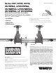
Install Instructions


2
Guidelines
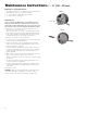
1. Most field problems occur because dirt and debris present in
the system at the time of installation becomes trapped in the
#1 check. The system should be flushed before the backflow
valve is installed. If the system is not flushed until after the
backflow valve is installed, remove both check modules from
the valve and open the inlet shutoff to allow water to flow for
a sufficient time to flush debris from the water line. If debris in
the water system continues to cause fouling, a strainer can
be installed upstream of the backflow assembly.
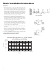
2. Watts models 957, 957RPDA and LF957RPDA may be in-
stalled in either horizontal, “N” pattern, or “Z” pattern position
as long as the backflow assembly is installed in accordance
with the direction of the flow arrow on the assembly and the
local water authority approves the installation.
3. The assembly should be installed with adequate clearance
around the valve to allow for inspection, testing and servic-
ing. 12" (305mm) should be the minimum clearance between
the lower portion of the assembly and the floor or grade. The
valve should be protected from freezing.
4. Installing a backflow preventer in a pit or vault is not recom-
mended.
5. Normal discharge and nuisance spitting are accommodated
by the use of a Watts air gap fitting and a fabricated indirect
waste line. Floor drains of the same size must be provided in
case of excessive discharge.
6. The 957 and 957RPDA backflow preventer should be tested
by a certified tester at the time of installation.
NOTE: Assembly body should not be painted.
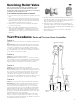
Horizontal Installation
N Pattern
Z Pattern
Basic Installation Instructions
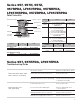
Relief Valve Discharge Rates 2
1
⁄2" – 10" (65 - 250mm)
957, 957RPDA and LF957RPDA
lpm gpm
1330 350
1140 300
950 250
760 200
570 150
380 100
190 50
0 0
0 20 40 60 80 psi
0 138 276 413 551 kPa
Rate of Flow
Pressure