
Troubleshooting guide


Page 9
Drain Saddle Installation - Fits standard 1 ¼” – 1 ½” drain pipes
Step 12
Step 13
Step 14
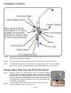
The drain saddle must be installed at least 1 ½” above the nut
of the P-Trap elbow or cross bar from the garbage disposal to
insure proper drainage. Using the 1/4” drill bit, drill into the drain
pipe at best available location as specied above, for drain saddle
installation. Take extreme caution to only drill through one side
of the drain pipe.
The small square black foam gasket with a circle cut out of the
middle must be applied to the inside of the drain saddle. Remove
sticky tape backing and stick to the drain saddle.
(See Picture to Right)
Locate the correct drain saddle kit in the parts bag.
If you have a garbage disposal, do not install the drain saddle near it.
Installation of the drain saddle must be either above the garbage disposal,
or if a second sink drain is available, install it above the cross bar on the
second drain. Installation of the drain saddle near a garbage disposal
may cause the drain line to plug.
Caution:
P-Trap
Elbow
Assemble the drain saddle around the drain pipe and align drain
saddle tting opening with the hole drilled in the previous
step - you may use a small screwdriver to feed through the drain
saddle into the drain pipe to aid with the alignment. Using a Phillips
screw driver tighten the drain saddle bolts evenly and securely on
both sides.
Step 15
1.5”
Caution:
Do not over tighten the screws. It may crack the drain saddle.
Follow all local plumbing codes for your installation.
Drain Saddle Tube Connection
In the parts bag locate the 1/4” red tube. Attach the end labeled
“Flow Capillary Inside” to the open compression Tee tting on the
lower RO membrane housing using a 5/8” wrench to tighten the
white plastic nut securely. Connect the other open end to the quick
connect tting on the drain saddle by pushing the tube all the way
to the tube stop.
Step 16
Green Tube Connection
Step 17
Insert the other open end of the green 1/4” tube into the open 1/4” quick connect tting on
the plastic adapt-a-valve making sure the tube is pushed in all the way to the tube stop.
Green Tube
Adapt-a-Valve
In the parts bag locate the 1/4” Green tubing. Connect the tube
to the RO system (left housing) by inserting it into the open 1/4”
quick connect tting on the housing lid. Make sure the tube is
pushed in all the way to the tube stop.
Step 18