
Owner`s manual


Watson Industries, Inc. GGC-E101 Rev A 08/30/2013
4
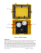
Heading Direction
Orientation
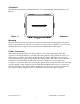
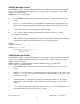
The GGC unit side that has carrying handle needs to be aligned along the heading direction. See
Figure 1.
Figure 1 – Alignment
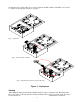
Mounting
The GGC-E101 case needs to be placed on a flat horizontal surface. Unsnapping the four plastic
clasps opens the GGC case. The case cover needs to be fully opened so that the cover is below the
antennas when they are deployed to avoid interference with the GPS satellite signals.
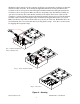
Power / Connectors
This unit has an internal regulator to allow operation over a wide voltage input range. Best
operation is obtained at either 24 or 28 VDC, although operation is fully satisfactory down to 15
VDC and up to 35 VDC. Power draw of the unit is about 7 Watts. The GGC power system is
isolated from the GGC signal system. The 65-meter mating cable (GGC Cable –65) for this unit is
included and coiled inside the lid. This cable needs to be attached to a power supply and a
computer to receive data. The cable is removed by opening the five straps that secure the cable. The
necessary length of cable can then be uncoiled. The Red and Black wires need to be connected to
the DC power Supply. The Orange, White and Brown wires need to be connected to the RS-232
port of data collection computer. For more information on the cable hookup see page 17.
Handle