VPAC User's Manual Solid State Relay Power Control Watlow Controls 1241 Bundy Boulevard, P.O. Box 5580, Winona, MInnesota USA 55987-5580 Phone: 507/454-5300, Fax: 507/452-4507 http://www.watlow.com 0600-0028-0000 Rev B December, 1999, North American English Supersedes: WVPC-XUMN Rev A00 $5.00 Made in the U.S.A.
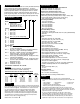
General Description Specifications The VPAC Series Power Controls are a family of Solid State Relay (SSR) controls for electric heating applications. The VPAC provides output power proportional to the input command signal from a temperature control. The single phase VPAC-01 can be ordered in either ON/OFF (solid state contactor), burst fired or phase angle firing mode. The three phase, two leg VPAC-32 is for solid state contactor or burst fired (loop powered) operation only.
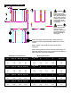
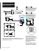
VPAC Dimensions and Mounting C Starting Out E ç UP ∫ WARNING: VPAC mounting and spacing must conform to local, state and national safety codes. Failure to conform to codes could result in death or personal injury, or damage to equipment. A H B ç CAUTION: W UP Mount units with heat sink fins oriented vertically. Failure to do so could result in unit failure and damage to the process.
Mount 120/240V Transformer AT+/BT Power Mount Semiconductor Fuses The AT+ or BT transformer powers the AT+ or BT control card. Mount the transformer within 12 in. (30.5cm) of the VPAC it connects to. Starting Out 0.4" 0.5" 0.2" 0.3" (12mm) for 15A, 30A fuse (13mm) for 50A fuses (6mm) for 15A, 30A fuses (8mm) for 50A fuses 0.2" (5mm) Mtg. Holes 1.7" (45mm) Panel 2.4" (60mm) 0.8" (21mm) 120/240V Xformer 16-0238 0.2" (56mm) 2.0" (51mm) 0.4" (10mm) 1.4" (35mm) Mount 15/30A Semiconductor Fuse 1.
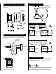
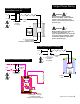
Single Phase Wiring Starting Out 1Ø Wiring for AC & DC Input Contactor 10-40A, Models (CA or CD) ç L1 ∫1 ∫2 ∫1 WARNING: L2 Semiconductor Fuse Limit Contactor L1 T1 Contacts (if required) CD Wiring must conform to National Electric Code (NEC) safety standards, as well as locally applicable codes. Failure to do so could result in death or personal injury. ç ∫2 WARNING Wiring examples show L2 in 240V~(ac) or 480 V~(ac) configuration.
Single Phase Wiring Starting Out 1Ø Wiring, 4-20mA Burst (BT) 1Ø Wiring, 4-20mA Phase Angle (AT+) ç ∫1 ∫2 Wiring must conform to National Electric Code (NEC) safety standards, as well as locally applicable codes. Failure to do so could result in death or personal injury, or damage to equipment.
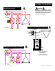
3-Phase, 2-Leg Wiring Starting Out ∫ 3Ø Wiring for AC & DC Input Contactor 10-40A, Models (CA or CD) ç Wiring must conform to National Electric Code (NEC) safety standards, as well as locally applicable codes. Failure to do so could result in death or personal injury, or damage to equipment.
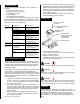
5. Troubleshooting To isolate a system problem involving the VPAC, answer these questions: • Are inputs to the VPAC present? • Are outputs from the VPAC present? • Are all connections good? • Is the load good? • Is line voltage within specification? • Are temperature control signals present? If so, then the VPAC power control itself may be the problem. The problem may be with the VPAC's control card, transformer or solid state relay. Use the table below to assist with troubleshooting.