Silver Series Operator Interface Terminals Addendum to Installation and Operation Manual Operator Interface Terminals 1241 Bundy Boulevard, Winona, Minnesota USA 55987 Phone: +1 (507) 454-5300, Fax: +1 (507) 452-4507 http://www.watlow.com 0600-0067-0000 Rev. D May 2011 ©2011 Watlow. All rights reserved.
TC Table of Contents Chapter 1: Introduction ..................................................................................3 Additional Resources .................................................................................3 Chapter 2: Install and Wiring .........................................................................4 Connecting via Modbus RTU (232/485) .....................................................4 Connecting via Modbus TCP (Ethernet)..............................................
1 Chapter 1: Introduction The Silver Series Operator Interface Terminals (OITs) are powerful human machine interfaces for equipment and processes. EasyBuilder5000 is easy-to-use and flexible software for creating the windows, buttons, displays, gauges and other screen items with which operators interact on the OIT. The purpose of this addendum is to quickly get you up and running with the OIT and software when used with Watlow controllers.
2 Chapter 2: Install and Wiring Consult the Silver Series Installation and Operation Manual for detailed information on installing and wiring the OITs. This chapter provides important additional information regarding connecting to and communicating with Watlow controllers. Connecting via Modbus RTU (232/485) The tables below indicate to which pins on the Silver Series OIT’s DB9 connectors the Watlow EZZONE® screw terminals should connect.
• The IP address is listed in the System settings window on the Network tab. (If Auto Get IP Address is selected, the IP Address is not editable. If you want to configure the OIT for a fixed address, select IP address get from below, and enter the IP address here. • Click OK to close the System settings window on the OIT. Hints for using the Virtual Keyboard to enter the OIT password and IP addresses: • If you do not see the Virtual Keyboard it may be minimized; click the X on the menu bar.
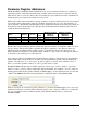
Parameter Register Addresses The Modbus RTU and Modbus TCP communications protocols assume that each device’s memory is organized in blocks of like-data. Each data block contains either read-only data or read/write data and either bit-size data or word-size (16-bit) data. For example, the Coils data block contains read/write bits and the Input Register data block contains read-only words. Within each of these data blocks there is a range of memory locations.
For example, the EZ-ZONE PM Integrated Controller Models User’s Manual lists the relative address for Heat Power as 1904. To monitor the heat power with the Silver Series OIT, you will add one (1) to the relative address and enter “1905” in the Address field in EasyBuilder5000. (073) In summary, when setting an address for a screen object to read or write from a Watlow controller: • For the Device type select 4x.
Choosing the Communications Drivers When you create a project using EasyBuilder5000 you select the drivers necessary to communicate with the Watlow controllers and any other devices with which the Silver Series OIT must communicate. For Watlow controllers, you select one of these drivers: • Modbus RTU Master—used with Watlow controllers that support Modbus RTU and communicate via RS-232 or RS-485. • Modbus TCP/IP Master—used with Watlow controllers that support Modbus TCP and communicate via Ethernet.
Address Offsets in Multi-Loop Controllers In controllers with more than one loop of control, more than one limit etc., there is more than one instance of each parameter for these duplicated functions. The manuals for controllers such as the EZZONE RM, list the Modbus address and an offset for these parameters. Add the offset to the address once to get the address of the second instance of the parameter, add it twice to get the third instance and so on.
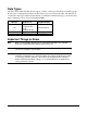
Data Types The Silver Series OIT’s Modbus drivers support a variety of data types. The Watlow manuals specify the data type of each parameter. However the terminology is not precisely the same. The table below correlates the data types indicated in the Watlow documentation with the data types you should select when configuring a screen object in EasyBuilder5000.
4 Chapter 4: Programming Tutorials The following sections guide you through creating a first project using EasyBuilder5000 and a Silver Series OIT that communicates with a Watlow controller. Create a First Project The following procedure guides you through the process of configuring a Silver Series OIT to communicate with a Watlow Controller. 1) To launch EasyBuilder5000: on the Windows task bar click Start, click All Programs, click Watlow, click EZware-5000 and click EasyBuilder 5000.
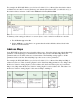
6) In the System Parameter Settings dialog, in the Device List, select the Local PLC 1 device and click Settings… (002) 7) For PLC type, choose the appropriate driver. See the table below. 8) For PLC I/F, choose the appropriate hardware interface. See the table below. 9) For PLC default station no. type the controller’s address. Typically this is 1 for the first controller.
For part numbers like… with… For PLC type choose… For PLC I/F choose… PMxxxxx-2xxxxxx EZKx-2xxx-xxxx RMAx-x2xx-xxxx Modbus RTU Modbus RTU Master RS-232 or RS-485 2W* PMxxxxx-3xxxxxx EZKx-3xxx-xxxx Modbus TCP Modbus TCP/IP Master Ethernet RMAx-x3xx-xxxx Other Watlow Controllers Modbus RTU Modbus RTU Master RS-232 or RS-485 2W* *Both 232 and 485 are available; choose the one to which you have connected the OIT.
15) Click OK to close the System Parameter Settings dialog. 16) Save the project: • From the File menu, choose Save. • In File name type First Project.mtp. • Click Save. Create a Popup Window This example assumes you have created a project that configured to communicate with a Watlow controller and that project is open in EasyBuilder5000. 1) From the Window menu, choose Open Window. 2) Click New… (006) 3) Click Base Window. (007) 4) Ensure the Name is Window_011 and the Window no. is 11.
9) In the Popup window group, set Start pos. Y to 120 (0 for the 4.3 in. OIT). 10) Click OK. 11) In the Open Window dialog, select Window_11. 12) Click Open. 13) From the File menu choose Save. Create a Meter in a Popup Window This example assumes you have created a popup window in a project that is configured to communicate with a Watlow Controller and that window is open in EasyBuilder5000. 1) From the Objects menu, choose Meter Display. 2) Click the General tab. 3) In Description type Heat Power.
10) Click the Outline tab. 11) In Degree set Start degree to 270. 12) In Degree set End degree to 90. 13) In Background uncheck Full circle. 14) In Tick marks check Enable. 15) For Tick marks Color, select black. 16) In Tick marks set Main scale to 6. 17) In Tick marks set Sub scale to 1. 18) In Tick marks set Length to 6. (010) 19) Click the Limits tab. 20) Set Value Zero to 0. 21) Set Value Span to 100. 22) Check Range limits Enable. 23) Set Width to 3. (011) 24) Click OK.
27) Double-click the meter to open the Meter Display Object’s Properties dialog. 28) Click the Profile tab. 29) Set X to 140. (012) 30) Set Y to 60. 31) Set Width to 140. 32) Set Height to 140. 33) Click OK. 34) From the File menu choose Save. Add a Numeric Display This example assumes you have created a window in a project that is configured to communicate with a Watlow Controller and that window is open in EasyBuilder5000. 1) On the Objects menu, click Numeric/ASCII then choose Numeric Display.
5) For Address choose 4x and enter the address of the Closed Loop Working/Active Set Point for your controller. See the table. 6) Click the Numeric Format tab. 7) In Data format set the data type. See the table. 8) On the Font tab set Align to Right.
Add Increment and Decrement Buttons This example assumes you have created a window in a project that is configured to communicate with a Watlow Controller and that window is open in EasyBuilder5000. To add a button that increments the set point: 1) On the Objects menu, click Button then choose Set Word. 2) Click the General tab. 3) In Description type Increment Set Point. 4) For PLC name choose Modbus RTU Master or Modbus TCP/IP Master. 5) Click Setting… 6) For Device type choose 4x.
16) Click Shape Library… 17) Click Select Lib… 18) Select Arrows 1.plb. 19) Click Open. 20) Locate the button with the triangular arrow pointing up and click it. 21) Click OK to close the Shape Library. (016) 22) Click OK to close the New Set Word Object dialog. 23) Click to place the button. 24) Use the handles to adjust the size of the button. 25) Drag the button to place it as desired on the screen. 26) From the File menu choose Save.
To add a button that decrements the set point: 1) Click the increment button to select it. 2) From the Edit menu, choose Copy. 3) From the Edit menu, choose Paste. 4) Drag the new button to an appropriate position. 5) Deselect the button by clicking on the window’s background or another item in the window. (018) 6) Double click the new button to edit its properties. 7) On the General tab change: • Description to Decrement Set Point • Set Style to Press and hold decrement (JOG--). 8) Set Bottom Limit to 0.
Add an Option List for Control Mode This example assumes you have created a window in a project that communicates with a Watlow Controller and that window is open in EasyBuilder5000. 1) On the Objects menu, click Button then choose Option List. 2) Click the General tab. 3) In Description type Control Mode. 4) Set Mode to Dropdown list. 5) Set No. of states to 3. 6) In the Control address group: • For PLC name choose Modbus RTU Master or Modbus TCP/IP Master. • Click Setting… • For Device type choose 4x.
8) In the Values column type the numeric and text values that corresponds to each option you want to include. See the table. 9) Click OK to close the New Option List Object dialog. (020) State 0 1 2 3 (error) Value 10 54 62 Enumerated Value Auto Manual Off 10) Position the cursor near the bottom center of the window layout and click to place the multi-state switch. (You may have to move the other objects around to fit everything.) 11) From the File menu choose Save.
Add a Button to Close the Popup Window This example assumes you have created a window in a project that communicates with a Watlow Controller and that window is open in EasyBuilder5000. 1) On the Objects menu, click Button then choose Function Key. 2) On the General tab, in Description type Close Window. 3) Select Close window. 4) On the Shape tab, uncheck Use shape. (023) 5) Check Use picture. 6) Click Picture Library… 7) Click Select Lib… 8) Select Computer.flb. 9) Click Open.
16) Click the Profile tab 17) Set Position X to 375. 18) Set Position Y to 5. 19) Set Size Width to 40. 20) Set Size Height to 40. 21) Click OK. 22) From the File menu choose Save. (025) Edit the Startup Window This example assumes you have created a popup window open in EasyBuilder5000 in a project that is configured to communicate with a Watlow Controller. To add text to the start up window: 1) From the Window menu, choose 1 10 – Initial. 2) From the Draw menu choose Text.
6) Position the cursor centered in the top third of the window layout and click to place the text. 7) From the File menu choose Save. Add a Numeric Display to the main window: 1) On the Objects menu, click Numeric/ASCII and choose Numeric Display. 2) Click the General tab. 3) In Description type Process Variable. (027) 4) For PLC name choose Modbus RTU Master or Modbus TCP/IP Master. 5) For Address choose 4x.and enter the address of the Analog Input 1 Process Value. See the table.
11) Move the cursor with the outline to position the display field in the center of the screen and click to place it. 12) From the File menu choose Save. (030) To create a function key on Window10: 1) On the Objects menu, click Button then choose Function Key. 2) On the General tab, in Description type Loop 1 Settings. 3) Select Display popup window. 4) For Style choose No title bar. 5) For Window no. select 11. Window_011. (031) 6) Click the Shape tab. 7) Check Use shape.
19) Position the cursor and click to place the function key. 20) From the File menu choose Save. (032) Compile and Download the Project This example assumes you have a project that is ready to compile and load into an OIT. To compile the project: 1) From the Tools menu, choose Compile. 2) Click Compile. 3) After the project is compiled, click Close.
• Connect the USB cable to a USB port on the computer. • If this is the first time you have connected the OIT to the computer via the USB port, locate a follow the procedure in the EasyBuilder 5000 help, “How Do I Install the Maple Systems USB driver?” 3) In EasyBuilder5000 from the Tools menu, choose Download. 4) Select Ethernet or USB cable. 5) For Ethernet, in HMI IP select or enter the OITs IP address. 6) Set Password to the OITs password (111111 by default). 7) Check Firmware, if not already checked.
To download the project via a USB drive to an OIT equipped with a USB Host port: 1) Connect at USB drive to the PC 2) From the Tools menu choose Build Data for USB Disk or CF Card Download… (038) 3) Click Browse… 4) Locate and select the USB drive. Note: Do not select a sub directory of the USB drive. Select the root. 5) Click OK to close the Browse For Folder dialog. (039) 6) Click Build. 7) When the files are transferred successfully, click OK. 8) Click Exit to close the USB Disk/CF Card Data dialog.
5) With the Virtual Keyboard enter the Password. (By default this is 111111.) Note: If you have difficulty entering the password, see the hints below. 6) On the Download Settings dialog make sure Download Project Files is checked. 7) Click OK. 8) In the Pick a Directory dialog expand the usbdisk folder by clicking the plus (+) next to it. 9) Select the folder that represents the USB drive in the usbdisk folder. Note: The OIT represents the USB drive with a folder icon and a name it assigns such as disk_a_1.
To copy data to the OIT’s local memory: 1) From the Objects menu choose Data Transfer (Timebased). 2) For each item to be logged in the file: • Click New… (041) • In Description type a description of the data to be copied such as “PV 1”. • For Address type choose Word. • For Interval choose a value that is the same as or less than the amount of time you want between data samples. • In No. of words type word size of the parameter’s data type. See table.
Note: Pick a range of addresses with room to store all the data that must be displayed. For example, use 200 for the first parameter to be logged then for each additional parameter increment the address by the size in words of the previous data. For example, typically you log floats such as process variables and set points which each require two words to store. In that case if the first process variable is copied to 200, set the next parameter to copy to 202 so on.
3) In Description type a description for the set of data such as “Loop 1”. 4) For Sampling mode choose Time-based. 5) For Sampling time interval choose the time between samples. 6) For Read address PLC name choose the OIT (“Local HMI” by default). 7) For Read address device type choose LW. 8) In Read address Address type the first address to which data was copied. In the example, this is 200. (045) 9) In Max. data records type the number of records to save in a file.
12) Click Exit to close the Data Format window. (048) 13) Check one or more locations to which to save the data (Save to USB 1 or Save to HMI memory). 14) In Folder name type a name for the folder in which the data log file should be created such as “datalog”. (049) 15) Click OK to close the Data Sampling Object set up window. 16) Click Exit to close the Data Sampling Object window.
3) Click Base Window. (007) 4) In Name type Trend. 5) Click OK. 6) In the Window list select Trend. 7) Click Open. (057) To create buttons to open the Trend window and return to the first window: 1) Select window 10. (064) 2) Select the function key on that screen by clicking it once. (065) 3) From the Edit menu, choose Copy. 4) From the Edit menu, choose Paste. 5) Place the copy next to the original. 6) Click on the screen background to deselect the button.
15) From the Edit menu, choose Copy. 16) Select window 12 Trend. 17) From the Edit menu, choose Paste. 18) Position the button centered at the bottom of the screen. 19) Edit the new button’s properties so that it changes to full-screen window 10 Initial and is labeled “Back”. To create a trend graph: 1) From the Objects menu choose Trend Display. 2) In Description type a description of the trend such as “Loop 1 PV, SP and Heat vs. Time”.
9) Click the Channel tab. 10) For each channel to be graphed: • In the Data sampling object group check Display. • For Color choose a color that contrasts with the background color. • In Zero type the value that should be graphed at the bottom of the yaxis. • In Span type the value that should be graphed at the top of the y-axis. 11) Click OK.
14) Optional: Use the Scale tool to add a scale and labels with the Text tool. Color coordinate these or add a legend if the trend channels don’t all have the same zero and span. (055) Use Recipes This example assumes you have a project with at least one controller in which the recipe memory has not already been used for something else. In this example we will create a recipe that has five parameters from one controller.
1) From the Objects menu choose Data Transfer (Triggerbased). 2) In Description type “Recipe Save:” and the name of the name of the parameter (such as “Loop 1 Set Point”. 3) For Source address PLC name choose Modbus RTU Master or Modbus TCP/IP Master. 4) For Source address choose 4x and enter the address of the parameter. 5) In No. of words type word size of the parameter’s data type. See Table. 6) Click Setting… 7) For Destination address PLC name choose the OIT (Local HMI by default).
11) Click OK to close the Address dialog 12) For Mode choose External Trigger. 13) For Trigger address PLC name choose the OIT (Local HMI by default). 14) For Trigger address Device type choose LB to use an internal bit to cause the OIT to store values in a recipe. 15) In Trigger address Address type 500. 16) Click the Label tab. 17) Check Use label. 18) Set State to 0. 19) In Content type the name of the parameter. 20) Click OK. 21) Place the Data Transfer (Trigger-based) object on the screen.
1) From the Objects menu choose Data Transfer (Triggerbased). 2) In Description type “Recipe Load:” and the name of the parameter (such as “Loop 1 Set Point”). 3) For Source address PLC name choose the OIT. 4) For Source address choose RW and type the recipe address for the item. (062) 5) If you set up the recipe save to use and index register: • Click Source address Settings… • Check Source address Index register • For Source address Index choose INDEX 0 (16-bit). • Click OK to close the Address dialog.
To create a button to trigger the data transfer objects to copy the values currently in the controller to the corresponding recipe memory in the OIT: 1) On the Objects menu, point to Button and choose Set Bit. 2) In Description type “Save Recipe”. 3) For PLC name choose the OIT (Local HMI by default). (063) 4) For Address choose LB and type 500. 5) For Set style Choose Momentary. 6) Click the Label tab. 7) Check Use label. 8) In Content for state 0 type “Save to OIT”. 9) Click OK. 10) Place the button.
Optional: To see what you are copying from the controller to the OIT’s recipe memory, create an object displaying the current value in the controller next to each Data Transfer (Trigger-based) object. Create a label that indicates what the fields are such as “Current Controller Values”. Optional: To see or edit directly what is saved in recipe memory create a data entry object for each recipe item. These objects should display the values of the data in the RW memory at the recipe addresses.
Address indexing allows a screen object to display and set the value of different memory locations depending on the value in the index. In this example we use LW-9200 as the address index. Whatever value the index is set to is added to the address in the data transfer (and recipe display) objects. When the index value is zero, the first recipe is used. When the index is 10 the second recipe is used. When the index is 20 the third recipe is used.
To select the recipe to save to or load from create a multi-state switch to select the recipe as follows: 1) On the Objects menu point to Buttons and choose Multi-State Switch. 2) In Description type “Recipe Selector”. 3) Click Read address Setting… 4) For PLC name choose the OIT (Local HMI by default). 5) Check System tag. 6) For Device type choose LW-9200 (16bit) : address index 0. (069) 7) Click OK to close the Address dialog.
17) Click Set… 18) For each state enter the appropriate offset Value. For state 0 enter 0. For state 1 enter a value that will offset the beginning of the second recipe beyond the end of the first in the recipe memory. 19) Click OK to close the State mapping window. (070) Note: The first recipe is selected with the multi-state switch in its state 0.
How to Reach Us Corporate Headquarters Europe Watlow Electric Manufacturing Company 12001 Lackland Road St. Louis, MO 63146 Sales: 1-800-WATLOW2 Manufacturing Support: 1-800-4WATLOW Email: info@watlow.com Website: www.watlow.com From outside the USA and Canada: Tel: +1 (314) 878-4600 Fax: +1 (314) 878-6814 Watlow France Tour d'Asnières. 4 Avenue Laurent Cély 92600 Asnières sur Seine France Tél: + 33 (0)1 41 32 79 70 Télécopie: + 33(0)1 47 33 36 57 Email: info@watlow.fr Website: www.watlow.