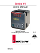
Series V4 Users Manual General Purpose 1/4 DIN Temperature Controller 1241 Bundy Boulevard, P.O. Box 5580, Winona, Minnesota USA 55987-5580 Phone: +1 (507) 454-5300, Fax: +1 (507) 452-4507, http://www.watlow.
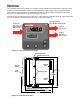
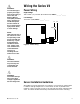
Overview The V4 1/4 DIN panel mount controller is a general purpose industrial PID temperature controller. The V4 provides a reliable cost-effective solution for most temperature control applications. Thermocouple, RTD, and Current and Voltage sensors are supported. Dual outputs can be configured to support heating and cooling. The secondary output can also be configured as an alarm.
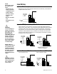
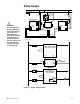
Installation and Removal 3.62" (92mm) V4 1 2 % Panel Cutout 3.93" (99.82mm) Panel Thickness 3.62" (92mm) 0.375" 9.5 mm) 0.85" (20mm) minimum 0.85" (20mm) minimum Figure 3 - Series V4 multiple panel cutout dimensions. NOTE: Measurements between panel cutouts are the minimum recommended. Installing the Series V4 Controller Installing and mounting requires access to the back panel. 1. Make the panel cutout using the panel cutout dimensions as shown in Figure 4. 2.
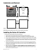
Installation and Removal (continued) Figure 4a - Slightly compress the case while pulling the controller into the panel cutout. Figure 4b - Snap the top and bottom mounting bracket into the slots. Figure 4c - Tighten screw to secure the controller. Figure 4d - Remove the controller using a flat screwdriver. NOTE: Be careful not to over-tighten the screws. This may cause the mounting cover to fail. Over-tightening occurs when the front bezel is touching the customer’s front panel.
ç WARNING: To avoid damage to property and equipment and/or injury or loss of life, use National Electric Code (NEC) standard wiring practices to install and operate this unit. Failure to do so could result in injury and/or death, or such damage.
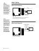
NOTE: Successful installation requires five steps: • Choose the controller’s hardware configuration and model number; Input Wiring Figure 6a – Thermocouple Extension wire for thermocouples must be of the same alloy as the thermocouple itself to limit errors. DIP Switch Orientation 1: OFF 2: ON • Choose a sensor; • Wire the controller and ç WARNING: 6 Figure 6b – RTD (2- or 3-Wire) 100Ω Platinum There could be a +2°F input error for every 1Ω of lead length resistance when using a 2-wire RTD.
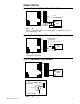
ç Output 1 Wiring WARNING: Figure 7a – Mechanical Relay To avoid damage to property and equipment and/or injury or loss of life, use National Electric Code (NEC) standard wiring practices to install and operate this unit. Failure to do so could result in injury and/or death, or such damage.
Output 1 Wiring Figure 8a – Switched DC, Open Collector 18 17 18 + 16 15 17 14 13 16 - External Load 15 12 OFF 14 4 5 8 6 7 13 V+ unregulated 18 V— NOTE: When an external device with a nonisolated circuit common is connected to the 4-20mA or dc output, you must use an isolated or ungrounded thermocouple.
Output 2 Wiring Figure 9a – Mechanical Relay Without Contact Suppression 18 18 17 17 16 15 16 14 15 COM 14 NC NO 13 12 OFF 13 4 5 8 6 7 Fuse L1 External Load Customer Supplied Quencharc L2 V4T _ - _ D _ _ - _ _ _ _ Form C, rated at 8A @ 125V~ (ac) or 5A @ 240V~ (ac).
Wiring Example L1 120V~(ac) L2 Earth Ground fuse high limit mechanical contactor fuse fuses coil V4TH-CAAA-AARR 18 Temperature Controller 16 94AA-1DK1-00RG Limit Controller 18 17 ç 16 14 13 TC OFF 12 5 (+) DIP Switch Orientation 4 5 8 6 7 6 (-) 8 L2 18 17 16 18 16 15 14 13 TC T2 OFF 12 WARNING: To avoid damage to property and equipment and/or injury or loss of life, use National Electric Code (NEC) standard wiring practices to install and operate this unit.
Keys and Displays Upper Display: Indicates the process value, actual temperature, operating parameter values or an open sensor. When powering up, the Process display will be blank for five seconds. • To set to blank, set [`dsP] to [`SEt] in the Setup Menu. Lower Display: Indicates set point, output value, parameters for data in the upper display, or error and alarm codes. • To set to blank, set [`dsP] to [`Pro] in the Setup Menu.
How to Set Up the Series V4 ∫ WARNING: Remove power from the controller before removing the chassis from the case or changing the DIP switches. Removing the controller from the chassis is not a normal operating condition and should only be done by a qualified technician. Setting up the Series V4 is a simple process. First set the DIP switches to match your input type. Refer to the orientation on the back of the controller to select the [``In] Input value.
Setup Parameters NOTE: Shaded parameters may not appear, depending on the controller’s configuration and model number. [`LOC} At the top of the Setup Menu the Series V4 displays the user level of operation in the upper display and the [`LOC] parameter in the lower display. Press the ‰Advance key and the value of the next parameter appears in the upper display, and the parameter appears in the lower display. Lock: Selects the level of operator lock-out as defined below.
{``rh} Range High: Selects the high limit of the operating range. Also used to scale the high end of the process input. 5.0VÎ (dc) and 20mA represent Range High [``rh] for a process input. The process input is linearly scaled between [``rL] and [``rH]. See the model number and specification information in the Appendix for your range values, or refer to the following table. Range: Sensor range high to [``rL] Default: High limit of sensor type for a thermocouple or RTD. 9999 for process input.
[`P`L] {`dSP} Table 15a Input Ranges. Power Limiting: The power limiting function in % power for heat only. Power Limiting will function if [`pb1] is set to [```0]. Range: Dependent on output type. 0 to100 Default: 100 Display: Selects which displays are active or viewable. Five seconds after selected, the appropriate display goes blank. Press ‰Advance, ¿Up-arrow or ¯Down-arrow to override this feature and cause the current value to be displayed for 5 seconds.
Figure 16 The Operation Menu. Operation Menu NOTE: The upper display will always return to the process value after 1 minute without key strokes. NOTE: Shaded parameters may not appear, depending on the controller’s configuration and model number.
If a mechanical relay or contactor is switching power to the load, a longer cycle time may be desirable to minimize wear on the mechanical components. Typical life of a mechanical relay is 100,000 cycles. Range: 0.1 to 999.9 seconds Default: 5.0 seconds {`ALO} Alarm Low: Represents the low process alarm or low deviation alarm. This parameter will not appear if [`Ot2] is set to no or [`Con].
Troubleshooting Alarms and Errors Indication Power Alarms • No power. Probable Cause(s) • • • • Power to unit may be off. Fuse may be blown. Breaker may be tripped. Safety interlock door switch, etc. may be activated. • Separate system limit control may be latched. • Wiring may be open. • Input Power may be incorrect. Corrective Action • Check switches, fuses, breakers, interlocks, limits, connectors, etc. for energized condition and proper connection. • Measure power upstream for required level.
Calibration Before attempting to calibrate, make sure you read through the procedures carefully and have the proper equipment called for in each procedure. Make sure the DIP switches are in the proper position for the input type. Entering the Calibration Menu In the Calibration Menu, various input signals must be supplied for the controller to go through its auto calibration. The Calibration Menu can only be entered from the [`LOC] Lock parameter in the Setup Menu.
Calibration Menu Figure 20 Calibration Parameters. Calibration Menu [``NO] [`YES] [`CAL] [`CAL] ‰ ‰ ‰ [`)00] Input 0.00mV for low input. [`5)0] Input 50.00mV for high input. [``tC] Connect a Type "J" ambient compensator with inputs shorted. [`440] Set the low resistance to 44.01Ω. [`225] Set the high resitance to 255.42Ω. [`)00] Set the voltage source to 0.000 volts. [`%00] Set the voltage source to 5.000 volts. [`$00] Set the cursource to 4.00mA [`2)0] Set the current source to 20.
RTD Field Calibration Procedure Equipment Required • 1KΩ precision decade resistance box with 0.01Ω resolution. NOTE: When the % indicator light is on, the controller is automatically calibrating. Your sequence is VERY important. Always move to the next parameter before changing the calibration equipment. Setup And Calibration 1. Connect the ac line voltage L1 and L2 to the proper terminals. 2. Connect the decade resistance box to Terminal 4, 5 and 6 on the terminal block.
4-20mA Input Field Calibration Procedure Equipment Required: • Precision current source 0-20mA minimum range with 0.01mA resolution. Setup and Calibration NOTE: When the % indicator light is on, the controller is automatically calibrating. Your sequence is VERY important. Always move to the next parameter before changing the calibration equipment. 1. Connect the ac line voltage L1 and L2 to the proper terminals on the V4. 2.
Specifications (1968) Control Mode • Microprocessor-based, user selectable control modes • Single process input, dual output • 2.
Operating Environment • 32 to 149°F (0 to 65°C) • 0 to 90% RH, non-condensing Storage Temperature • -40° to 185°F (-40° to 85°C) Terminals • Touch-safe, plugable terminal blocks • 22 to 12 AWG Controller Weight • 0.68 lb (310g) Shipping Weight • 0.75 lb (0.34 kg) Dimensions • 1⁄4 DIN size and NEMA 4X2 front panel make the Series V4 easy to apply and maintain in a wide variety of applications. Unique mounting brackets, gasket and collar make installation a snap. Overall Height: 4.3 inches (109 mm) Width: 4.
Declaration of Conformity Series V4 WATLOW SINGAPORE PTE LTD Asia Controls 55, Ayer Rajah Crescent, #03-23 Ayer Rajah Industrial Estate Singapore 139949 Declares that the following product: English Designation: Series V4 Model Number(s): V4T(H or L)-(C D F or K) (A C D or K) AA-AA (Any two letters or numbers) Classification: Control, Installation Category II, Pollution Degree II Rated Voltage: 100 to 240V~ (ac) or 24Vı (ac/dc) Rated Frequency: 50/60 Hz.
Safety Information We use note, caution and warning symbols throughout this book to draw your attention to important operational and safety information. NOTE: A “NOTE” marks a short message in the margin to alert you to an important detail. Details of a “Note” appear here in the narrow margin on the outside of each page. A “CAUTION” safety alert appears with information that is important for protecting your equipment and performance.