Series SD31 User’s Manual Single Display PID Controller with Optional Countdown Timer TOTAL CUSTOMER CUS ER SATISF TISFACTI CTION 3 Year Warranty ISO 9001 Registered Company Winona, Minnesota USA 1241 Bundy Boulevard., Winona, Minnesota USA 55987 Phone: +1 (507) 454-5300, Fax: +1 (507) 452-4507 http://www.watlow.com 0600-0041-0010 Rev. C January 2007 Made in the U.S.A. $15.
Safety Information We use note, caution and warning symbols throughout this book to draw your attention to important operational and safety information. A “NOTE” marks a short message to alert you to an important detail. ç CAUTION or WARNING Ó Electrical Shock Hazard CAUTION or WARNING A “CAUTION” safety alert appears with information that is important for protecting your equipment and performance. Be especially careful to read and follow all cautions that apply to your application.
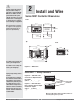
TC Table of Contents Chapter 1: Overview . . . . . . . . . . . . . . . . . . . . . . . . . .2 Chapter 2: Install and Wire . . . . . . . . . . . . . . . . . . . . .4 Chapter 3: Keys and Displays . . . . . . . . . . . . . . . . .14 Home Page Overview . . . . . . . . . . . . . . . . . . . . . .15 Adjusting the control set point . . . . . . . . . . . . . . . .15 Operations Page Overview . . . . . . . . . . . . . . . . .16 Setup Page Overview . . . . . . . . . . . . . . . . . . . . . .
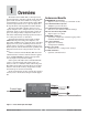
1 Overview The Watlow Series SD31 PID, is a microprocessorbased temperature controller available in the 1/32 DIN panel mount size. The Series SD31 has a single, universal input that accepts various thermocouples, RTDs (resistive temperature devices) or process inputs. (See the Specifications in the Appendix for further details). The Series SD31 PID controller offers up to two outputs. Outputs can be configured as heat, cool, timer, retransmit, alarm or off (deactivated).
How to use the Series SD31 controller Before you use your Series SD31 controller, it must be installed and configured correctly. Which setup steps you need to perform will depend on how you will use it. If you purchased the controller to design into your products: You will need to do the first three steps and maybe some of the fourth step. Some wiring, such as the final wiring of a communications connection or an alarm output for signaling an external device, might be left to the end user.
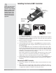
ç Caution: Follow the installation procedure exactly to guarantee a proper IP65/NEMA 4X seal. Make sure the gasket between the panel and the rim of the case is not twisted and is seated properly. Failure to do so could result in damage to equipment. Note: Contact your local Greenlee supplier for the appropriate punch kit and cutout tools required for rapid mounting. 2 Install and Wire Series SD31 Controller Dimensions Front 53.6 mm (2.11 in) 45.0 to 45.6 mm (1.77 to 1.79 in) Panel Cutout 30.7 mm (1.
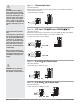
ç Installing the Series SD31 Controller Caution: Follow the installation procedure exactly to guarantee a proper IP65/NEMA 4X seal. Make sure the gasket between the panel and the rim of the case is not twisted and is seated properly. Failure to do so could result in damage to equipment. Panel Mounting Bracket Mounting Tab Mounting Ridge Gasket Bezel Case Arrows indicate the direction of pull to remove the connectors. IP65/NEMA 4X Seal Example 1.
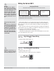
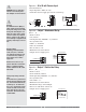
Ó Wiring the Series SD31 Warning: Use National Electric (NEC) or other country-specific standard wiring and safety practices when wiring and connecting this controller to a power source and to electrical sensors or peripheral devices. Failure to do so may result in damage to equipment and property, and/or injury or loss of life. Spring clamp wiring connector note: To insert the wire, push the wire into the desired connection number, and it should automatically lock into place.
ç (all model numbers) Thermocouples are polarity sensitive. The negative lead (usually red) must be connected to terminal 11. • Input impedance: >20 MΩ 4 +10 -11 10 11 5 6 7 8 9 10 11 6 8 9 1011 Warning: Use National Electric (NEC) or other country-specific standard wiring and safety practices when wiring and connecting this controller to a power source and to electrical sensors or peripheral devices. Failure to do so may result in damage to equipment and property, and/or injury or loss of life.
ç (all model numbers) • Input impedance 100 Ω, dc only • Controller does not supply power for the current loop 4 - 11 8 9 1011 Warning: Use National Electric (NEC) or other country-specific standard wiring and safety practices when wiring and connecting this controller to a power source and to electrical sensors or peripheral devices. Failure to do so may result in damage to equipment and property, and/or injury or loss of life.
ç Figure 9a — Output 1 Switched DC Warning: Use National Electric (NEC) or other country-specific standard wiring and safety practices when wiring and connecting this controller to a power source and to electrical sensors or peripheral devices. Failure to do so may result in damage to equipment and property, and/or injury or loss of life.
ç Warning: Use National Electric (NEC) or other country-specific standard wiring and safety practices when wiring and connecting this controller to a power source and to electrical sensors or peripheral devices. Failure to do so may result in damage to equipment and property, and/or injury or loss of life. Figure 10a — Output 2 Solid-state Relay SD31 - _ _ K _ - _ _ _ _ • Form A contact • 0.
Selecting an EIA/TIA-232 to EIA/TIA-485 Converter 12 V GN Î ( GND dc) TD D ( TD B) (A ) When choosing an EIA/TIA 232 to 485 converter, look for one with the following features: Two-wire capability EIA/TIA-485 can be implemented as a two-wire system or a four-wire system. Most Watlow controllers, including the Series SD31, use two-wire communications when working with EIA/TIA-485. The converter selected must have a two-wire mode. Some converters can only be used in a four-wire mode.
Ethernet Gateway The EM00-GATE-0000 is a bridge that allows up to 32 Watlow controllers to be directly connected to an Ethernet network. The gateway provides a bridge for Modbus messages between the Ethernet bus and EIA-485 or EIA-232 links. The Gateway supports full product configuration monitoring and configuration of runtime parameters via MODBUS TCP over TCP/IP using a software package such as Watlow’s WATVIEW™. The Series SD31 can be configured using WATVIEW with or without the EM Gateway.
Notes: Watlow Series SD31 ■ 13 ■ Chapter 2 Install and Wire
3 Keys and Displays Four Digit, LED Display: • Indicates process value or set point information SDXX or • Page name, prompt name or prompt value, depending upon the key combination pressed. 1 2 RDY % SET Timer Indication (timer option only) Colon indicates status of timer. Set Key Press to view set point, process or parameter values, depending on [~dsp} setting. Release ß Key to view page or parameter information.
Home Page Overview The Home Page is the default display of the Series SD31 controller. The Home Page can be configured to display either the process value or set point value. (see the {~Dsp} prompt on the Setup Page.) This parameter determines what parameters and values are displayed. % Automatic Mode The % indicator light is off. * **Press ß Key [``75] [``75] To adjust the set point: Actual temperature Set point value (Use Up ¿ or Down ¯ keys to raise or lower the set point.) 1.
Operations Page Overview [Oper] The Operations Page contains parameters accessed during normal day-to-day operation. The Series SD31 provides a patented user-definable menu system, allowing the user to customize the Operations Page contents. To go to the Operations Page, press and hold the Infinity Key ˆ for about three seconds from the Home Page. • Press the Down ¯ or Up ¿ keys to move through the Operations Page parameters. • To view or change a parameter value, press and hold the ß Key.
Setup Page Overview [`SEt] The Setup Page contains parameters that define basic controller functions. Go to the Setup Page for initial configuration or if your application requirements change. Be sure to program the Setup Page first! Always press the Infinity Key ˆ to return to the Home Page. You must start from the Home Page. To go to the Setup Page, press both the Up ¿ and Down ¯ keys for about three seconds. • Press the Down ¯ or Up ¿ keys to move through the Setup Page parameters.
Programming Page Overview [Prog] The Programming Page determines what parameters the user wants to appear on the Operations Page. Select a parameter for any of the 20 Programming Page locations, P1 to P20. These now appear on the Operations Page. All 20 locations have parameters selected as defaults. To go to the Programming Page, hold down the Infinity key ˆ, then press the SET Key ß, and hold both down for about six seconds.
4 Home Page Press the Infinity Key ˆ at any time to go to the Home Page. Depending upon the controller’s status, you will see some combination of the parameters listed below. Normally, you will see the Process Value in the display. See Home Page Overview in Chapter Three. After 60 seconds with no key presses, the controller reverts to the Home Page. Display Parameter Name Description Settings Range Default Modbus* (less 40,001 (Integer values for Modbus offset) in parenthesis.
Display Parameter Name Description Settings Range Default Modbus* (less 40,001 (Integer values for Modbus offset) in parenthesis.) Read/Write Appears if: [rP;tg] Ramp Target Set Point The target set point for the ramp that is in process appears in the display after this prompt appears. Set Point Low Limit [SP;Lo] to Set Point High Limit [SP;hi] NA Same as Closed Loop Set Point Controller is ramping. [Er;In] Input Error Indicate an input error state.
5 Setup Page To go to the Setup Page, press both the Down ¯ and Up ¿ keys for three seconds from the Home Page. [`SEt] will appear in the display. • Press the Down ¯ or Up ¿ keys to move through the Setup Page parameters. • To view or change a parameter value, press and hold the ß Key. • Press the Down ¯ or Up ¿ keys to change the parameter value. • Press the Infinity Key ˆ at any time to return to the Home Page.
Display Parameter Name Description Settings Range (Integer values for Modbus in parentheses.) Default Modbus* Appears if: (less 40,001 offset) Read/Write [Sc;Lo] [Sc.Lo] Process Scale Low Set the low scale for process inputs. 0.00 to 20.00 mA: if [`Sen] 4.00 mA is set to [`mA] (0000 to 20000) 0.00V 0.00 to 10.00V: if [`Sen] is set to [uoLt] (0000 to 10000) *73, 74 R/W (mA) *77, 78 R/W (V) [`Sen] is set to [`mA] or [uolt[. [Sc;hi] [Sc.
Display Parameter Name Description Settings Range (Integer values for Modbus in parentheses.) Default Modbus* Appears if: (less 40,001 offset) Read/Write [ti;En] [ti.En] Timer Enable Set to enable the countdown timer function. [`~no] no (0) [~YEs] yes (1) [`~no] (0) 391 R/W Timer model only, SD31-XXXX-XTXX. [`Ot1] or [`Ot2]is set to [tim]. [hour] [hour] Countdown Time Hours Set the number of hours for the countdown time. 0-99 hours (0 to 99000) 0 392 R/W Timer model only, SD31-XXXX-XTXX.
Display Parameter Name Description Settings Range (Integer values for Modbus in parentheses.) Default Modbus* Appears if: (less 40,001 offset) Read/Write Control Method 1 Set output 1 control type. This parameter is only used with PID control, but can be set anytime. [`Ftb] Fixed Time Base (0) [`Ftb] (0) [Urtb] Variable Time Base (1) [Ftb1] [Ftb1] Fixed Time Base 1 (Cycle Time) Set the time base for Fixed Time Base Control. 1.0 to 60.0 seconds if Out- 20.0: mech.
Display Parameter Name Description Settings Range (Integer values for Modbus in parentheses.) Default Modbus* Appears if: (less 40,001 offset) Read/Write [r1;h ; i] [r1.hi] Output 1 Retransmit High Scale Set the high scale for the retransmit output. -1999.0 to 9999.0 (-1999000 to 9999000) 0 *308, 309 R/W Output 1 is a process output (SD_ _ - _ _ _ F - _ _ _ _ ) and [Ot`1] is set to [rmt] . [r1;C ; O] [r1.CO] Output 1 Retransmit Offset Set the high scale for the process output. -999.0 to 999.
Display Parameter Name Description Settings Range (Integer values for Modbus in parentheses.) Default Modbus* Appears if: (less 40,001 offset) Read/Write [PSH2] [PSH2] Output Power Scale High 2 Set the high end of the range within which the output will scale. 0.0 to 100.0% 100.0% [Ot`2] is set to [hEAt] or [CooL], [Ctr2] is set to [`Ftb] and Output 2 is not a communications output.
Display Parameter Name Description Settings Range (Integer values for Modbus in parentheses.) Default Modbus* Appears if: (less 40,001 offset) Read/Write [Lgc2] [Lgc2] Alarm 2 Logic Select the alarm output condition in the alarm state. [AL`C] closed on alarm [AL`O] open on alarm [AL`C] [Ot`2] is set to [dE;AL] or [Pr;AL]. [LAt2] [LAt2] Alarm 2 Latching Turn alarm latching on or off. [nLAt] non-latching - off [`LAt] latching - on [nLAt] [Ot`2] is set to [dE;AL] or [Pr;AL].
Display Parameter Name Description Settings Range (Integer values for Modbus in parentheses.) Default Modbus* Appears if: (less 40,001 offset) Read/Write [``rP] [ rP] Ramping Mode Select when the control set point ramps to the defined end set point. [`OFF] off (0) [`OFF] (0) [`Str] ramps on start-up only (1) [``On] ramps at start-up or any set point change (2) 266 R/W Always active. [rP;Sc] [rP.Sc] Ramp Scale Select the scale of the ramp rate.
6 Operations Parameters Table These parameters can be selected to appear on the Operations Page. Select parameters to appear on the Operations Page on the Programming Page. To go to the Operations Page, press and hold the Infinity Key ˆ for three seconds from the Home Page. [Oper] will appear in the display. • Press the Down ¯ or Up ¿ keys to move through the Operations Page parameters. • To view or change a parameter value, press and hold the ß Key.
Display Parameter Name Description Settings Range (Integer values for Modbus in parentheses.) Rate Heat Set the PID rate time in minutes for the heat output. 0.00 to 9.99 minutes (0000 to 9990) Derivative Heat Set the PID derivative time in minutes for the heat outputs. 0.00 to 9.99 minutes (0000 to 9990) [dB;ht] [dB.ht] Dead Band Heat An offset of the heating proportional band from the set point. [h;hyS] Default Modbus* Appears if: (less 40,001 offset) Read/Write 0.
Display Parameter Name Description Settings Range (Integer values for Modbus in parentheses.) Rate Cool Set the PID rate time in minutes for the cool outputs. 0.00 to 9.99 minutes (0000 to 99990) Derivative Cool Set the PID derivative time in minutes for the cool outputs. 0.00 to 9.99 minutes (0000 to 99990) [dB;Cl] [db.CL] Dead Band Cool An offset of the cooling proportional band from the set point. [C;hyS] Cool Hysteresis Set the control switching hysteresis for on/off control.
Display [A1;hi] [A1.hi] Parameter Name Description Alarm 1 High Set the high alarm set point. Settings Range (Integer values for Modbus in parentheses.
Display Parameter Name Description Settings Range (Integer values for Modbus in parentheses.) Countdown Time - Seconds Set the number of seconds remaining for the countdown time. 0 to 59 seconds (0 to 59000) Closed Loop Timer Set Point Set the set point to be used during the timer sequence if the controller is in the auto mode. [Ot;SP] [Ot.SP] [`rdy Default Modbus* Appears if: (less 40,001 offset) Read/Write 377 R Timer model only, SD31-XXXX-XTXX. [`Ot1] or [`Ot2]is set to [tim].
7 Programming Page The Programming Page allows you to select what parameters appear on the Operations Page. To go to the Programming Page, press the ß key and Infinity ˆ keys for six seconds from the Home Page. {Prog} will appear in the display. • Press the Up ¿ or Down ¯ keys to move through the parameter prompts, P1-P20. • To change a parameter value, press and hold the ß key, and press the Up ¿ or Down ¯ keys to change the value.
Programming Page Example An oven manufacturer wants users of their ovens to have easy access to the Series SD PID parameters. They also want to limit access to other parameters they do not want users to change. This can be achieved by customizing the Operations Page. The Programming Page configuration determines which parameters appear on the Operations Page. The static set point version (SD_C-_ _ _ _- _ _ _ _) has 20 Programming Page locations, P1 to P20.
8 Countdown Timer The optional countdown timer (SD31-XXXX-XTXX only) provides a versatile timer function that allows countdown timing that can toggle set points and trigger outputs based on timer settings. During timing, the controller can automatically change to a different set point, and then revert to the original set point after timing completes.
Prompt Timer Enable {ti;En} [ti.En] Hours {hour} [hour] Minutes [Min] [Min] Seconds [~Sec] [ Sec] Timer Start Method [ti;St] [ti.St] Timer Related Settings Set to {~~On} to enable the timer. Set the number of hours for the countdown time. Set the number of minutes for the countdown time. Set the number of seconds for the countdown time. [Imd] Immediate Method - Timer sequence starts on a Down ¯ key press at the Home Page. Timer countdown starts immediately. Timer does not make use of the Ready Band.
Prompt Timer Related Settings Timer Set Point [ti;SP] [ti.SP] [~Off] Set Point Off - The normal control set point will continue to be displayed, but the SD31 will use a set point of "Off" during the timing sequence. [trAc] Set Point Tracking - Uses the same set point both in and out of the timer sequence. [Pre;S] Preset Set Point - Allows programming of a set point for use in the timer sequence and a separate set point for use outside of the timer sequence.
Prompt Timer Related Settings Timer Output Function [ti;F1], [ti;F2] [ti.F1] , [ti.F2] Each timer output can independently have its timer output function selected. Delay On, Delay Off, Signal On, and Signal Off. Delay On [dl;On] [dl.On] Output is energized before timer sequence; de-energized during timer sequence; energized after timer sequence. [dl;On] Delay ON Timer Output is ON before timing; OFF during timing; ON after timing. Delay Off [dl;OF] [dl.
Prompt Timer Related Settings Signal Time - Minutes [S;M1], [S;M2] [S.M1], [S.M2] Set the number of minutes for the signal time. Signal time appears with the Signal On and Signal Off timer output functions. This is the time for which a timer output will either be energized or de-energized at the end of the timer countdown. Each timer output can independently have a signal time programmed. Signal Time -Seconds [~S;S1], [~S;S2] [ S.S1], [ S.S2] Set the number of seconds for the signal time.
Prompt Timer Related Settings Closed Loop Timer Set Point [Ct;SP] [Ct.SP] Sets the set point that will be used during the timer sequence when the controller is in the automatic control mode and the Timer Set Point, [ti;SP] , is set to Preset Set point, [Pre;S]. Open Loop Timer Set Point [Ot;SP] [Ot.SP] Sets the manual power level that will be used during the timer sequence when the controller is in the manual mode and the Timer Set Point, [ti;SP] , is set to Preset Set point, [Pre;S].
Timer Example Convection Oven Application A master chef bakes bread at 350 F for 30 minutes. She wants the oven at the proper temperature with an indication when it is ready to begin baking. She isn't concerned if the oven is 10 degrees cool at first. After she loads the oven, the chef wants to start the countdown time by pressing a key. When the baking time is complete, she wants a 10-second audible indication that the bread is done.
9 Factory Page and Calibration To go to the Factory Page, press both the Down ¯ and Up ¿ keys for six seconds from the Home Page. [`SEt] will appear in the display after three seconds. Continue to hold both keys until [FAct] appears in the display. • Press the Down ¯ or Up ¿ keys to move through the Factory Page parameters. • To view or change a parameter value, press and hold the ß Key. • Press the Down ¯ or Up ¿ keys to change the parameter value.
Display Parameter Name Description Settings Range (Integer values for Modbus in parentheses.) Default Modbus* Appears if: (less 40,001 offset) Read/Write Output 2 Type Displays the hardware type for Output 2. [nonE] none (0) [~~DC] DC/open collect. (1) [rLAY] mech. relay (2) [~SSr] solid-state relay (3) [COM] communications (5) [nonE] (0) 203 R Always active. [O.ty2] [`S;id] [ S.id] Software ID Displays the software ID number. 0 to 9999 (0 - 9999) NA 10 R Always active.
Display [``A;4] [ A.4] [`A;16] [ A.16] [O1;1u] [O1.1v] [O1;9u] [O1.9v] [O1;4A] [O1.4A] [O1;16] [O1.16] Parameter Name Description Settings Range (Integer values for Modbus in parentheses.) Default Modbus* Appears if: (less 40,001 offset) Read/Write Input Calibrate, 4.0 mA Calibrate the process current input to 4.0 mA (see “Calibrating the Series SD31”). [``no] [`yes] [``no] *NA Always active. Input Calibrate, 16.0 mA Calibrate the process current input to 16.0 mA.
Calibrating the Series SD31 RTD Input Procedure Warm up the unit for 20 minutes. To reach the calibration parameters, enter the Factory Page by pressing and holding both the Down Key ¯ and Up Key ¿ for six seconds. Once on the Factory Page [FACT], use the Down Key ¯ to select a parameter. Press and hold the ß Key to view or change the parameter value. The last parameters on the Factory Page are the input and output calibration parameters.
Current Process Input Procedure Equipment • Precision current source, 0 to 20 mA range, with 0.01 mA resolution. Input Setup and Calibration 1. Connect the correct power supply to terminals 1 and 2 (see Chapter Two). 2. Connect the current source to terminals 11(-) and 8(+). 3. Enter 4.00 mA from the current source to the controller. Allow at least 10 seconds to stabilize. Press the Down Key ¯ until the Input Calibrate 4 mA parameter, [``A;4] appears.
10 Features Saving and Restoring User Settings . . . . . . . . . . . . . . . . . . .49 Operations Page . . . . . . . . . . . . . . . . . . . . . . . . . . . . . . . . . . .49 Autotuning . . . . . . . . . . . . . . . . . . . . . . . . . . . . . . . . . . . . . . . .49 Manual Tuning . . . . . . . . . . . . . . . . . . . . . . . . . . . . . . . . . . . . .50 Inputs . . . . . . . . . . . . . . . . . . . . . . . . . . . . . . . . . . . . . . . . . . . .50 INFOSENSE™ Temperature Sensing . . . . . . . . . . . . .
Saving and Restoring User Settings 4. Press and hold the ß Key and change [`~no] to [SEt1] or [SEt2] by pressing the Down Key ¯. The default parameters will automatically appear on the Operations Page. To change the list of parameters appearing on the Operations Page, hold down the Infinity key ˆ, then press the Advance Key ‰, and hold both down for about six seconds until [Prog] appears in the display. This is the Programming Page. Press the Down Key ¯ once to go to the first Programming Page selection.
In some applications, the autotune process may not come up with PID parameters that provide the process characteristics you desire. If the autotune does not provide satisfactory results, you will have to perform a manual tune on the process: 1. Apply power to the Series SD31 and establish a set point typically used in your process. 2. Go to the Operations Page, and establish values for the PID parameters: Proportional Band = 5; Reset* = 0.00; Rate* = 0.00. Note: Autotune should be set to off. 3.
Filter Time Constant Filtering smoothes an input signal by applying a first-order filter time constant to the signal. The displayed value, the controlled value or both the displayed and controlled values can be filtered. Filtering the displayed value makes it easier to monitor. Filtering the signal may improve the performance of PID control in a noisy or very dynamic system. Select filter options with Input Filter [Ftr;E]. Select the Filter Value with [FLtr] (Setup Page).
Control Methods Output Configuration Each controller output can be configured as a heat output, a cool output, an alarm output or deactivated. No dependency limitations have been placed on the available combinations. The outputs can be configured in any combination. For instance, all three could be set to cool. Analog outputs can be scaled for any desired current range between 0 and 20 mA or voltage range between 0 to 10V. The ranges can be reversed to high-to-low for reverse acting devices.
To transfer to auto mode from manual mode, press the Infinity Key ˆ to get to the Operations Page. Press the Down Key ¯ until [A-M] appears in the display. Press and hold the ß Key to display [Man] for manual mode. Use the Up ¿ or Down ¯ keys to select [Auto] . The automatic set point value will be recalled from the last automatic operation. Changes take effect after three seconds or immediately upon moving to the next parameter or by pressing the Infinity Key ˆ.
Proportional plus Integral plus Derivative (PID) Control Use derivative (rate) control to minimize the overshoot in a PI-controlled system. Derivative (rate) adjusts the output based on the rate of change in the temperature or process value. Too much derivative (rate) will make the system sluggish. Rate action is active only when the process value is within twice the proportional value from the set point. Adjust the derivative with Derivative Heat [dE;ht] or Derivative Cool [dE;Cl] (Operations parameters).
Independent Heat and Cool PID 100 90 Power Limit 100% Power Scale Low 15% Power Scale High 80% 80 Percent Power Output In an application with one output assigned to heating and another assigned to cooling, each will have a separate set of PID parameters and separate dead bands. The heating parameters take effect when the process temperature is lower than the set point and the cooling parameters take effect when the process temperature is higher than the set point.
Alarms Alarms are activated when the process value or temperature leaves a defined range. A user can configure how and when an alarm is triggered, what action it takes and whether it turns off automatically when the alarm condition is over. Configure alarm outputs on the Setup Page before setting alarm set points. Process or Deviation Alarms The combination of variable time base output and a solid-state relay can inexpensively approach the effect of analog, phase-angle fired control.
Alarm Hysteresis Alarm Silencing An alarm state is triggered when the process value reaches the alarm high or alarm low set point. Alarm hysteresis defines how far the process must return into the normal operating range before the alarm can be cleared. Alarm hysteresis is a zone inside each alarm set point. This zone is defined by adding the hysteresis value to the alarm low set point or subtracting the hysteresis value from the alarm high set point.
Communications Overview A Series SD31 controller can also be programmed and monitored by connecting it with a personal computer or programmable logic controller (PLC) via serial communications. To do this it must be equipped with an EIA/TIA 485 (SD_ _ - _ _ U_ - _ _ _ _) communications option for Output 2. Your PC or PLC must have available an EIA/TIA-485 interface or use an EIA/TIA-232 to EIA/TIA-485 converter. See “Selecting an EIA/TIA-232 to EIA/TIA-485 converter” in Chapter 2.
5. Configure the software’s communications parameters. A software package, (be it software for a Computer, a PLC or an OIT) will need to be configured just as the controller was configured, setting the Baud Rate and Address to match. The software package may have additional parameters to set, such as number of data bits, parity and stop bits. For Watlow controllers using modbus, these should always be set at 8 data bits, no parity, and 1 stop bit. This is often written as “8N1”.
Troubleshooting Indication Probable Cause(s) Corrective Action No power. Controller appears dead. No display indication in either window. Power to unit may be off. Fuse may be blown. Breaker may be tripped. Safety interlock door switch, etc. may be activated. Separate system limit control may be latched. Wiring may be open. Input power may be incorrect. Check switches, fuses, breakers, interlocks, limit devices, connectors, etc. for energized condition and proper connection.
Indication Probable Cause(s) Corrective Action Getting alarm message [A1hi], [A2hi], [A1Lo], or [A2Lo] . The process value is beyond an alarm set point. Determine when alarms messages will display and the proper response to an alarm message. Alarm is occurring when it should not. Alarm settings are incorrect. Adjust the alarm settings to be correct for the application. Input may be in an error condition. See error messages. Alarm may be latched. Press the Infinity Key ˆ to unlatch an alarm.
Error Messages Indication Probable Cause(s) Corrective Action [Er;In] Input error The sensor may be improperly wired. Sensor wiring may be reversed, shorted or open. The input may be set to the wrong sensor or the controller may not be calibrated. Calibration may have been corrupted. Check sensor connections. Check sensor connections and sensor wiring. Change Sensor Type [`Sen] (Setup Page) to match the sensor hardware. Restore factory calibration.
A Appendix Specifications • Controller • • • • • • • • • 1/32 DIN, microprocessor-based, user-selectable control modes Heat and cool autotune for control outputs 1 Universal input, 2 outputs Control outputs user-selectable as on-off, P, PI, PID Display update: 10 Hz, adjustable digital filter Output update: burst, 0.1 to 999.
• • • • • • • • • • • • Terminals Electromechanical Relay, Form A Minimum load current: 10 mA 2 A @ 240VÅ (ac) or 30VÎ (dc) maximum, resistive 125 VA pilot duty, 120/240VÅ (ac), inductive Must use RC suppression for inductive loads Electrical life 100,000 cycles at rated current • • • Process Range selectable: 0 to 20 mA, 4 to 20 mA, 0 to 5VÎ (dc), 1 to 5VÎ (dc), 0 to 10VÎ (dc) Reverse or direct acting 0 to 10VÎ (dc) voltage output into 1,000 Ω minimum load resistance 0 to 20 mA current output into 80
Ordering Information and Model Numbers S Power Supply H or L H 100 to 240VÅ (ac) L 24V‡ (ac/dc) Output 1 C, K, F or J C Switched DC K Solid-state Relay Form A, 0.5 Amp F Universal Process J Mechanical Relay Form A, 2 Amp Output 2 A, C, K, J or U A None C Switched DC K Solid-state Relay Form A, 0.
Index AC Line Frequency 27 AC Power Wiring 6 Access Lockout 28, 51 Active Output Indicator Lights 14 Address 28, 58 Adjust the set point 15 Adjusting the set temperature 15 Advance Key 14 Agency Approvals 64 Alarm 1 High 32 Alarm 1 Hysteresis 26 Alarm 1 Latching 26 Alarm 1 Logic 26 Alarm 1 Low 32 Alarm 1 Message 26 Alarm 1 Silencing 26 Alarm 2 High 32 Alarm 2 Hysteresis 26 Alarm 2 Latching 27 Alarm 2 Logic 27 Alarm 2 Low 32 Alarm 2 Message 27 Alarm 2 Silencing 27 Alarm High 1 Status 20 Alarm High 2 Status 2
Output Configuration 52 Output Nonlinear Function 1 24, 55 Output Nonlinear Function 2 26, 55 Output Power Scale High 1 24, 54 Output Power Scale High 2 26, 54 Output Power Scale Low 1 24, 54 Output Power Scale Low 2 26, 54 Output Timer Function 1 25 Output Timer Function 2 26 Output Types 63 Overview 2 Paktron 8, 9, 10 PI Control 53 PID Control 54 Power Cool 29, 55 Power Limit 1 24 Power Limit 2 25 Power limiting 54 Power scaling 54 Power specifications 64 Power Type 44 Power Up Method 37 Power Wiring 6 Pr
Prompt Index [``A;4] 45, 47 [`A;16] 45, 47 [A1;hi] 20, 32 [A1;Lo] 20, 32 [A2;hi] 20, 32 [A2;Lo] 20, 32 [ACLF] 27, 56 [Ac;ti] 27, 40 [Addr] 28, 58 [A;ma] 43 [AMb] 43 [A;mn] 43 [A-m] 29, 52 [AO1;U] 24 [A;Ot1] 43 [`Aut] 29, 49 [bAud] 28, 58 [`Cal] 29, 50 [CC;SP] 41, 42 [`C-F] 21 [C;hyS] 31 [CL;m] 30, 53 [Ctr1] 24 [Ctr2] 25 [Ct;SP] 33, 41 [dB;Cl] 31, 54 [dB;ht] 30, 54 [``dE] 31 [dE;Cl] 31, 54 [dE;ht] 30, 54 [dFLt] 43 [dL;OF] 25, 39 [dL;On] 25, 39 [`dSP] 27 [dSP1] 26 [dSP2] 27 [DSPL] 43 [Er;Ab] 62 [Er;Cs] 62 [Er
Declaration of Conformity Series SD Watlow Winona, Inc. 1241 Bundy Blvd.
How to Reach Us Your Authorized Watlow Distributor: TOTAL CUSTOMER SATISFACTION 3 Year Warranty Corporate Headquarters in the U.S.: Watlow Electric Manufacturing Co. 12001 Lackland Road St. Louis, Missouri, USA 63146 Telephone: +1 (314) 878-4600 Fax: +1 (314) 878-6814 Europe: Watlow GmbH Industriegebiet Heidig Lauchwasenstr. 1, Postfach 1165 Kronau 76709 Germany Telephone: +49 (0) 7253-9400 0 Fax: +49 (0) 7253-9400-44 Watlow France S.A.R.L.