Series SD Family Calibration Manual PID, PID Profiling, DeviceNet, and Limit Controllers TOTAL CUSTOMER CUS ER SATISF TISFACTI CTION 3 Year Warranty ISO 9001 Registered Company Winona, Minnesota USA 1241 Bundy Boulevard., Winona, Minnesota USA 55987 Phone: +1 (507) 454-5300, Fax: +1 (507) 452-4507 http://www.watlow.com 0600-0041-0030 Rev. A August 2003 Made in the U.S.A. $5.
Safety Information We use note, caution and warning symbols throughout this book to draw your attention to important operational and safety information. A “NOTE” marks a short message to alert you to an important detail. A “CAUTION” safety alert appears with information that is important for protecting your equipment and performance. Be especially careful to read and follow all cautions that apply to your application.
Factory Page and Calibration This Calibration Manual applies to all Series SD controllers, including the PID, PID Profiling, DeviceNet and Limit controller versions. For the user’s manual, go to www.watlow.com and search on Series SD User’s Manual. To go to the Factory Page, press both the Up ¿ and Down ¯ keys for six seconds from the Home Page. {Fact} will appear in the upper display and {page} in the lower display. • Press the ‰ Advance Key to move through the parameter prompts.
Display Parameter Name Description Settings Range (Integer values for Modbus in parentheses.) Default Modbus* Appears if: (less 40,001 offset) Read/Write Output 2 Type Displays the hardware type for Output 2. [nonE] none (0) [~~DC] DC/open collect. (1) [rLAY] mech. relay (2) [~SSr] solid-state relay (3) [COM] communications (5) [nonE] (0) 203 R Always active. Output 3 Type Displays the hardware type for Output 3. [nonE] (0) [nonE] none (0) [~~DC] DC/open collect. (1) [rLAY] mech.
Display [``U;9] [ v.9] [``A;4] [ A.4] [`A;16] [ A.16] [O1;1u] [O1.1v] [O1;9u] [O1.9v] [O1;4A] [O1.4A] [O1;16] [O1.16] [O3;1u] [O3.1v] [O3;9u] [O3.9v] [O3;4A] [O3.4A] [O3;16] [O3.16] Parameter Name Description Settings Range (Integer values for Modbus in parentheses.) Default Modbus* Appears if: (less 40,001 offset) Read/Write Input Calibrate, 9.0 Volt Calibrate the process voltage input to 9.0 Volt (see “Calibrating the Series SD”). [``no] [`yes] [``no] *NA Always active.
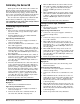
Calibrating the Series SD Warm up the unit for 20 minutes. To reach the calibration prompts, enter the Factory Page by holding down the Up Key ¿ and Down Key ¯ for six seconds. Once in the Factory Page [FACT], use the Advance ‰ key to select a prompt. The last prompts on the Factory Page are the input and output calibration prompts. You can restore the original factory calibration with Restore Factory Calibration [rESt] (Factory Page).
Process Output Procedures Equipment • Precision volt/ammeter with 3.5-digit resolution. Output 1 Setup and Calibration 1. Connect the correct power supply to terminals 1 and 2 (see Chapter Two). Volts 2. Connect the volt/ammeter to terminals 7 (-) and 6 (+). 3. At Output 1 Calibrate, 1V [01;1u] select [~YES] and press the Advance Key ‰. The voltage output value appears in the upper display. Press the Up ¿ or Down Key ¯ to adjust the upper display value to match the value from the volt/ammeter.
How to Reach Us Your Authorized Watlow Distributor: TOTAL CUSTOMER CUS ER SATISF TISFACTI CTION 3 Year Warranty Corporate Headquarters in the U.S.: Watlow Electric Manufacturing Co. 12001 Lackland Road St. Louis, Missouri, USA 63146 Telephone: +1 (314) 878-4600 Fax: +1 (314) 878-6814 Europe: Watlow GmbH Industriegebiet Heidig Lauchwasenstr. 1, Postfach 1165 Kronau 76709 Germany Telephone: +49 -7253-9400-0 Fax: +49 -7253-9400-44 Watlow France S.A.R.L.