Series PD Quick Start Guide Ethernet-Enabled Temperature/Process Controller TOTAL CUSTOMER CUS ER SATISF TISFACTI CTION 3 Year Warranty ISO 9001 Registered Company 1241 Bundy Boulevard., Winona, Minnesota USA 55987 Phone: +1 (507) 454-5300, Fax: +1 (507) 452-4507 http://www.watlow.com 0600-0043-0000 Rev. A April 2003 Winona, Minnesota USA Made in the U.S.A. $10.
Safety Information We use note, caution and warning symbols throughout this book to draw your attention to important operational and safety information. A “NOTE” marks a short message to alert you to an important detail. ç CAUTION or WARNING Ó Electrical Shock Hazard CAUTION or WARNING A “CAUTION” safety alert appears with information that is important for protecting your equipment and performance. Be especially careful to read and follow all cautions that apply to your application.
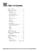
TC Table of Contents Chapter 1 - Overview . . . . . . . . . . . . . . . . . . . . . . . . . .2 Chapter 2 - Install and Wire . . . . . . . . . . . . . . . . . . . .3 Dimensions . . . . . . . . . . . . . . . . . . . . . . . . . . . . . . .3 Mounting the Series PD . . . . . . . . . . . . . . . . . . . . .4 Removing the Series PD . . . . . . . . . . . . . . . . . . . . .4 Series PD Connector Locations . . . . . . . . . . . . . . .5 Wiring the Series PD . . . . . . . . . . . . . . . . . . . . . . .6 Power . . .
1 Overview The Series PD controller is a DIN rail mounted, general purpose industrial PID temperature/ process controller. The Series PD is available in single and dual channel versions and features an embedded web server to provide an easy to use interface for configuration and monitoring of processes. The controller also features several popular communications protocols to facilitate easy integration into most existing process management systems.
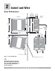
2 Install and Wire Series PD Dimensions bracket for panel mounting (M3.5 or #6 screw required) 8.1 mm (0.32 in) Top/bottom mount hole offset Side View PD PID Controller Power Ethernet Link 107.7 mm (4.24 in) 95.3 mm (3.75 in) DIN rail Ethernet Activity 1 Input Error 2 Input Error 118.3 mm (4.66 in) Output 1 Output 2 Output 3 Output 4 Address 128.4 mm (5.06 in) Min. Clearance between rail Front View centerlines 146 mm (5.75 in) Min. Clearance 51 mm (2 in) 41.6 mm (1.64 in) 73.
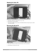
Mounting the Series PD Figure 4a — Mounting 1. Push unit in and down to catch rail hook on top of rail. 2. Rotate bottom of unit toward rail. 3. Rail clasp will audibly “snap” into place. If the Series PD does not snap into place, check to see if the rail is bent. Removing the Series PD Figure 4b — Removal 1. Press down on back of the Series PD until the bottom hook clears the rail. 2. Rotate bottom up and away from rail.
Series PD Connector Locations Two connectors on the bottom of the unit provide connection points for the input power, inputs and outputs. These connectors are removable and each terminal position is numbered. The RJ-45 connector is located on the top of the Series PD to allow connection to an Ethernet network.
Ó Wiring the Series PD Warning: Use National Electric (NEC) or other country-specific standard wiring and safety practices when wiring and connecting this controller to a power source and to electrical sensors or peripheral devices. Failure to do so may result in damage to equipment and property, and/or injury or loss of life.
(all model numbers) Thermocouples are polarity sensitive. The negative lead (usually red) must be connected to terminal 9. • Input impedance: >20 MΩ 10 + 9 - 9 10 11 12 Warning: Use National Electric (NEC) or other country-specific standard wiring and safety practices when wiring and connecting this controller to a power source and to electrical sensors or peripheral devices. Failure to do so may result in damage to equipment and property, and/or injury or loss of life.
Warning: Use National Electric (NEC) or other country-specific standard wiring and safety practices when wiring and connecting this controller to a power source and to electrical sensors or peripheral devices. Failure to do so may result in damage to equipment and property, and/or injury or loss of life. Figure 8a — 2-Wire RTD Input 2 (100 Ω DIN curve 0.00385 Ω/Ω/°C) PDD _-_ _ _ _-_ _ _ _ Terminals 5 and 7 must be shorted for a two-wire RTD.
Warning: Use National Electric (NEC) or other country-specific standard wiring and safety practices when wiring and connecting this controller to a power source and to electrical sensors or peripheral devices. Failure to do so may result in damage to equipment and property, and/or injury or loss of life.
ç Warning: Use National Electric (NEC) or other country-specific standard wiring and safety practices when wiring and connecting this controller to a power source and to electrical sensors or peripheral devices. Failure to do so may result in damage to equipment and property, and/or injury or loss of life.
Warning: Use National Electric (NEC) or other country-specific standard wiring and safety practices when wiring and connecting this controller to a power source and to electrical sensors or peripheral devices. Failure to do so may result in damage to equipment and property, and/or injury or loss of life.
ç Warning: Use National Electric (NEC) or other country-specific standard wiring and safety practices when wiring and connecting this controller to a power source and to electrical sensors or peripheral devices. Failure to do so may result in damage to equipment and property, and/or injury or loss of life. Figure 12a — Current Transformer Input 2, Single Phase • Input impedance 100Ω, Vac only The current transformer must be purchased separately.
ç Figure 13a — Output 1 Mechanical Relay Warning: Use National Electric (NEC) or other country-specific standard wiring and safety practices when wiring and connecting this controller to a power source and to electrical sensors or peripheral devices. Failure to do so may result in damage to equipment and property, and/or injury or loss of life.
ç Figure 14a — Output 1 Open Collector PD_ _ - C_ _ _ - _ _ _ _ 13 14 15 • Maximum current sink 250 mAÎ (dc) Warning: Use National Electric (NEC) or • Maximum supply voltage 42VÎ (dc) other country-specific standard • Output does not supply power wiring and safety practices when Class 2 power source wiring and connecting this conrequired for agency Power troller to a power source and to compliance. Supply electrical sensors or peripheral + Open Collector devices.
ç Figure 15a — Output 2 Solid-state Relay Warning: Use National Electric (NEC) or other country-specific standard wiring and safety practices when wiring and connecting this controller to a power source and to electrical sensors or peripheral devices. Failure to do so may result in damage to equipment and property, and/or injury or loss of life. • Form A contact PD_ _ - _ K _ _ - _ _ _ _ • 0.
ç Figure 16a — Output 3 Mechanical Relay Warning: Use National Electric (NEC) or other country-specific standard wiring and safety practices when wiring and connecting this controller to a power source and to electrical sensors or peripheral devices. Failure to do so may result in damage to equipment and property, and/or injury or loss of life.
ç Figure 17a — Output 3 Open Collector PD_ _ - _ _ C _ - _ _ _ _ Power Supply + - 19 20 21 • Maximum current sink 250 mAÎ (dc) Warning: Use National Electric (NEC) or • Maximum supply voltage 42VÎ (dc) other country-specific standard • Output does not supply power wiring and safety practices when Class 2 power source required for agency wiring and connecting this concompliance. troller to a power source and to Open Collector electrical sensors or peripheral 42VÎ (dc) maximum devices.
ç Figure 18a — Output 4 Solid-state Relay Warning: Use National Electric (NEC) or other country-specific standard wiring and safety practices when wiring and connecting this controller to a power source and to electrical sensors or peripheral devices. Failure to do so may result in damage to equipment and property, and/or injury or loss of life. • Form A.contact PD_ _ - _ _ _ K - _ _ _ _ • 0.
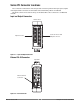
3 Indicator Lights The Series PD controller may have up to nine LED indicator lights to help you monitor the status of input power, Ethernet functions, input errors and outputs status. These LEDs can provide a quick visual indication of basic controller functions. Power Green light stays lit when the power is on. • If not lit or flashing, check your power source. Ethernet Link: Green light is lit if the Ethernet cable is correctly wired and connected to a 10BaseT port.
4 Ethernet Communications Network security is a critical issue for any network. Be sure to work with your network administrator to ensure that you follow best security practices to ensure a secure network environment. Here are some items to consider when installing Ethernet based controls on any network. • Use private IP addresses. • Separate the process network(s) from business network(s). • If external access is required, then have a single point of access to the process network.
Serial number Type PD012345 PDxx-xxxx-xxxx SN: 012345 DC: YYWW Auxiliary Inputs 1. 2. 3. 4. Input 2 5. 6. 7. 8. Input 1 Browse at address Type PD012345 TC-/S3/V-/ITC+/S1 I+/S2 V+/Info.Data W LO onnectivity -solutions Browse at: http://PD012345 Made In USA MAC Address: 00:01:23:45:67:89 WAT 9. 10. 11. 12. MAC Address Type WAT456789 Figure 21 — Browse at address, MAC address, and Serial number locations 6.
5 Troubleshooting Indication Probable Cause(s) Corrective Action Power LED not lit. Controller appears dead. No communications to PC. • Power supply switch off. • Fuse blown. • Breaker tripped. • Safety interlock door switch activated. • Separate system limit control latched. • Wiring incorrect or open. • Power supply voltage incorrect. • Defective controller. • Turn switch on. • Replace fuse (check cause of failure). • Reset breaker (check cause of failure). • Close door. • Reset limit controller.
Indication Alarm will not activate or clear. Probable Cause(s) • Controller is in Error condition. • Alarm is in latched setting. • Alarm is silenced. • Incorrect configuration. • Incorrect wiring. • Wrong output type. • Defective controller. Controller's process value reading is decreasing as the actual process is increasing. • Thermocouple is reversed wired. Controller does not control close enough to set point. • PID values incorrect. • Analog voltage or current input scaling is reversed.
6 Appendix Specifications (2341) Controller • Microprocessor based user-selectable control modes • Single or dual channel universal inputs • Current transformer inputs to monitor heater currents • Digital inputs • Up to four programmable outputs • Update rates, inputs = 10Hz, outputs = 10Hz Operator Interface • Browser based HMI (human machine interface) Standard Conditions For Specifications • Ambient temperature 25°C (77°F) ±3°C, rated line voltage, 50 to 60Hz, 0 to 90% RH non-condensing, 15-minute warm
Output Types Open Collector • Maximum voltage: 42VÎ (dc) • Maximum current: 500 mA • Class 2 power source required Switched DC • Supply voltage : 24VÎ (dc) @ 30 mA • Supply voltage maximum: 28VÎ (dc) into an infinite load Solid-state Relay • Optically isolated • Zero cross switched • Without contact suppression • Minimum load current: 500 µA rms • 0.
Ordering Information P Control Type S S or D Single channel D Dual channel Auxiliary Inputs A, 1, 2 or 3 A 1 None Dual digital inputs 2 One CT input and one digital input 3 Dual CT inputs (dual channel only) Output 1 C, K, F or J C K Switched dc, open collector SSR, Form A, 0.5 A F Universal process J Mechanical relay, Form A, 2 A Output 2 A, C, K or E A C None Switched dc, open collector K SSR, Form A, 0.
Declaration of Conformity Series PD Watlow Winona, Inc. 1241 Bundy Blvd.
How to Reach Us Your Authorized Watlow Distributor: TOTAL CUSTOMER CUS ER SATISF TISFACTI CTION 3 Year Warranty Corporate Headquarters in the U.S.: Watlow Electric Manufacturing Co. 12001 Lackland Road St. Louis, Missouri, USA 63146 Telephone: +1 (314) 878-4600 Fax: +1 (314) 878-6814 Europe: Watlow GmbH Industriegebiet Heidig Lauchwasenstr. 1, Postfach 1165 Kronau 76709 Germany Telephone: +49 (0) 7253-9400 0 Fax: +49 (0) 7253-9400-44 Watlow France S.A.R.L.