Series L User’s Manual Series L - Temperature Limit TOTAL CUST CUS TOMER SATISF TISFA ACTI CTIO ON 3 Year Warranty ISO 9001 Registered Company 1241 Bundy Boulevard., Winona, Minnesota USA 55987 Phone: +1 (507) 454-5300, Fax: +1 (507) 452-4507 http://www.watlow.com 0600-0044-0001 Rev. G February 2008 Winona, Minnesota USA Made in the U.S.A. $5.
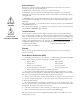
Safety Information We use note, caution and warning symbols throughout this book to draw your attention to important operational and safety information. A “NOTE” marks a short message to alert you to an important detail. ç CAUTION or WARNING Ó Electrical Shock Hazard CAUTION or WARNING A “CAUTION” safety alert appears with information that is important for protecting your equipment and performance. Be especially careful to read and follow all cautions that apply to your application.
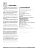
1 Overview Watlow's Series L family of temperature limit controllers* provide an economical limit controller solution for applications where thermal system protection is needed. A limit controller is added to applications to prevent over or under temperature conditions. The limit provides safety assurances against instances where a thermal runaway condition occurs as a result of a failed sensor, controller or output device.
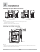
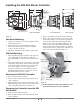
2 Installation Installing the Open Board Controller 61.7 mm (2.43 in) 61.7 mm (2.43 in) 45.07 mm (1.775 in) 56.3 mm (2.22 in) 61.7 mm (2.43 in) 45.07 mm (1.775 in) 56.3 mm (2.22 in) SWDC+ .6 N.O. 55.9 mm (2.20 in) 61.7 mm (2.43 in) SWDC- .7 COM 55.9 mm (2.20 in) N.C. .8 L1 L2 .9 .10 Terminal Designation Sticker Use M2.5 (#4) mounting hardware, not included Terminal Designation Sticker Use M2.5 (#4) mounting hardware, not included Screw Terminal Model Spade Terminal Model Figure 2a 1.
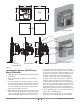
Installing the DIN Rail Mount Controller 81.8 mm (3.22 in) 94.7 mm (3.73 in) 78.1 mm (3.08 in) To install or remove, press down here. See Installing/ Removing the DIN Rail Controller procedures below. 90.7 mm (3.57 in) 39.1 mm (1.54 in) Part Number Label 80.0 mm (3.07 in) DIN rail, upper mounting clip 101.6 mm (4.00 in) 80.3 mm 112.3 mm (3.16 in) (4.42 in) 1. SW-1 2. SW-2 35 mm x 7.5 mm DIN rail is not included with the assembly 3.TC-/S1 4.TC+/S2 5.
72.4 mm (2.85 in) 68.0 mm (2.68 in) Panel Cutout Panel Thickness 1.52 to 3.18 mm (0.060 to 0.125 in) 72.4 mm (2.85 in) 68.0 mm (2.68 in) 19.1 mm (0.75 in) minimum 19.1 mm (0.75 in) minimum Spade Terminal Model Customer Front Panel Part Number Label 84.5 mm square (3.33 in) Terminal Blocks Locations on Screw Terminal Models Mounting Bracket 6.4 mm (0.25 in) Tactile Key, Screw Terminal Model 19.2 mm (0.76 in) 51.7 mm (2.04 in) Spade Terminal Model Figure 4 1.
is also seated properly and not twisted. The hardware installation is complete. Proceed to the wiring section. 2. Insert the controller into the panel cutout. 3. While pressing the bezel firmly against the panel, slide the mounting bracket over the back of the controller. Be sure the levers on the mounting bracket line up with the teeth on the case. 4. Press the bracket up to the back of the panel. The controller should fit tightly in the panel cutout. Removing the Panel Mount Square 1/8 DIN Controller 1.
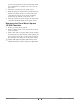
3 Wiring Ó Warning: Use National Electric (NEC) or other country-specific standard wiring and safety practices when wiring and connecting this controller to a power source and to electrical sensors or peripheral devices. Failure to do so may result in damage to equipment and property, and/or injury or loss of life. Note: Insulated terminals required for quick connect style terminals. For quick connect terminals 1, 2, 6, 7, 8, 9, and 10, AMP P/N 3-520406-2 or equivalent recommended.
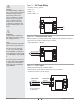
ç Figure 7a — AC Power Wiring Warning: Use National Electric (NEC) or other country-specific standard wiring and safety practices when wiring and connecting this controller to a power source and to electrical sensors or peripheral devices. Failure to do so may result in damage to equipment and property, and/or injury or loss of life.
ç Warning: Use National Electric (NEC) or other countryspecific standard wiring and safety practices when wiring and connecting this controller to a power source and to electrical sensors or peripheral devices. Failure to do so may result in damage to equipment and property, and/or injury or loss of life. Note: Use of an external reset switch may affect FM approval. Only the use of a momentary N.O. switch is valid for approval. Figure 8a — External Reset Switch • Momentary normally open (N.O.
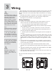
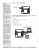
System Wiring Examples Power Disconnect Switch L1 120V~(ac) L2 Fuse Customer Supplied Quencharc Fuse Not used 1 2 Fuse High Limit Mechanical Contactor coil Fuse 6 SWDC+ SWDC7 8 L2 9 TC- 3 TC+ 4 5 10 Reset Switch (customer supplied) SW-1 SW-2 L1 + SSR-240-10A-DC1 in out Solid-State Relay Series CV Temperature Controller CVB1JH00000100C 1 2 TC- N.O. COM 7 N.C.
4 User Interface LV _ (1, 2, 5 or 6) _ _ _ _ _ _ _ _ _ _ A LIMIT LV LED Display: Indicates the limit set point. SET/RESET Key: Press and hold key to adjust the limit set point temperature. New limit set point is entered 3 seconds after the knob stops moving. Press key to reset latched limit output once tempera-ture is back in safe region. Can also be reset through customer supplied external reset switch.
Troubleshooting Indication Probable Cause(s) Corrective Action On indicating limits, the display is not illuminated. • Power supply switch off. • Fuse blown. • Breaker tripped. • Safety interlock door switch activated. • Wiring incorrect or open. • Power supply voltage incorrect. • Defective limit. • Turn switch on. • Replace fuse (check cause of failure). • Reset breaker (check cause of failure). • Close door. • Check wiring. • Verify input power • Repair or replace limit.
Indication Probable Cause(s) Corrective Action Troubleshooting RTD inputs Temperature reading is incorrect, showing a sensor error, [Er;In] , or ALARM LED is switching at the wrong temperature. • Setting for degree C or F is incorrect. Check model part number for Degree C or F. If the model has Increment/Decrement keys, then the C/F setting is adjustable. • Sensor or limit may be bad. Sensor connections may be bad. • Place a 110 ohm resistor across the sensor input terminals.
Specifications Controller • Microprocessor based, limit controller. • Nominal switching hysteresis, typically 1.7°C (3°F) • High or low limit, factory selectable. • Latching output requires manual reset upon over or under temperature condition. • Manual or automatic reset on power loss, factory selectable. • Internal front panel or external customer supplied momentary reset switch. • Input filter time: 1 second. Operator Interface (model dependent) • Four digit , 7 segment LED displays, .28" high.
Power • 24VÅ (ac) +10%; -15%; 50/60 Hz, ±5% • 120VÅ (ac) +10%; -15%; 50/60 Hz, ±5% • 208 to 240VÅ (ac) +/-10%, Series LF and CF only • 230 to 240VÅ (ac) +10%; -15%; 50/60 Hz, ±5% • 10VA maximum power consumption. • Data retention upon power failure via nonvolatile memory. Operating Environment • 0 to 70°C (32 to 158°F) • 0 to 90% RH, non-condensing. • Storage temperature: -40 to 85°C (-40 to 185°F) Dimensions • DIN Rail model can be DIN rail or chassis mount DIN rail spec, DIN 50022, 35 mm x 7.5 mm (1.
Ordering Information and Model Numbers Limit Control no user interface L F _ _ _ _ _ _ _ _ A A A A _ Set Point Type F Fixed Limit Set Point Line Voltage C 120VÅ (ac) E 230 to 240VÅ (ac) G 24VÅ (ac) Controller Package 1 Panel Mount, Square 1/8 DIN, Spade Terminals 2 DIN Rail Mount, Spade Terminals 3 Open Board, not potted, Spade Terminals 4 Potted Case, Spade Terminals 5 Panel Mount, Square 1/8 DIN, Screw Terminals 6 DIN Rail Mount, Screw Terminals 7 Open Board, not potted, Screw T
Ordering Information and Model Numbers Limit Control, LED display, front panel reset switch L V _ _ _ _ _ _ _ _ _ _ _ _ _ Set Point Type V Variable Limit Set Point Line Voltage C 120VÅ (ac) E 230 to 240VÅ (ac) G 24VÅ (ac) Controller Package 1 Panel Mount, Square 1/8 DIN, Rotary Knob, Spade Terminals 2 DIN Rail Mount, Rotary Knob, Spade Terminals 5 Panel Mount, Square 1/8 DIN, Rotary Knob, Screw Terminals 6 DIN Rail Mount, Rotary Knob, Screw Terminals A NEMA 4X/IP65, Panel Mount, Tacti
Declaration of Conformity Series L Watlow Winona, Inc. 1241 Bundy Blvd.
Declaration of Conformity Raymond D.
How to Reach Us Corporate Headquarters Europe Watlow Electric Manufacturing Company 12001 Lackland Road St. Louis, MO 63146 Sales: 1-800-WATLOW2 Manufacturing Support: 1-800-4WATLOW Email: info@watlow.com Website: www.watlow.com From outside the USA and Canada: Tel: +1 (314) 878-4600 Fax: +1 (314) 878-6814 Watlow France SARL Immeuble Somag 16, Rue Ampère 95307 Cergy-Pontoise CEDEX France Tel: + 33 (0)1 30 73 24 25 Fax: + 33 (0)1 30 73 28 75 Email: info@watlow.fr Website: www.watlow.