
Owner manual


Watlow Series N7 ■ 25 ■ Appendix
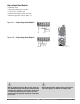
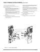
Install or Replace the Ethernet Module (Z100-0816-0000)
Ethernet Module Connector
Ethernet Module Circuit Board
Circuit Board Spacer
N7 Main Circuit Board
RJ-485 Ethernet
Connector
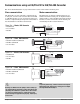
1. Remove power from the controller.
2. Pre-assemble the circuit board spacers onto the
Ethernet circuit board.
• Insert the pointed end of a circuit board spacer
into one of the four mounting holes of the
Ethernet circuit board from the side of the cir-
cuit board that has the label on it.
• Using firm pressure seat the circuit board spac-
er until the head of the spacer is flush with the
surface of the Ethernet circuit board.
• Repeat with the remaining three circuit board
spacers.
3. Install the Ethernet circuit board.
• Align the Ethernet connector with the Ethernet
module connector.
• Align the pointed ends of the four circuit board
spacers with the four mounting holes on the
main circuit board.
• While maintaining alignment of the Ethernet
connectors and the circuit board spacers, firmly
press the Ethernet circuit board onto the main
circuit board.
•Verify that the Ethernet connector and the cir-
cuit board spacers are seated properly.
4. Verify Output Wiring.
• Install RJ-485 Ethernet connector.
5. Test the Controller.
• Reapply power to the controller and test.
Figure 25 — Install the Ethernet Module.