
Owner manual

Watlow Series N7 ■ 15 ■ Chapter 2: Install and Wire
Ó
Warning: Use National Electric (NEC) or other country-spe-
cific standard wiring and safety practices when wiring and
connecting this controller to a power source and to electri-
cal sensors or peripheral devices. Failure to do so may
result in damage to equipment and property, and/or injury
or loss of life.
Ó
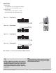
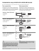
Warning: All high-voltage outputs must be powered by the
same source (phase), as shown in the example above.
1
2
3
45
6
Load
L1
L2
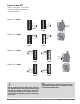
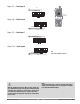
Figure 15d — High-voltage Control Output 4
1
2
3
45
6
Load
L1
L2
Figure 15c — High-voltage Control Output 3
1
2
3
45
6
Load
L1
L2
Figure 15b — High-voltage Control Output 2
1
2
3
45
6
Load
L1
L2
Figure 15a — High-voltage Control Output 1
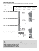
HV Control Out 1 HV Control Out 2 HV Control Out 3 HV Control Out 4
N7_ _ - _ _ _ _ - 2 _ _ _ mechanical relay mechanical relay mechanical relay mechanical relay
N7_ _ - _ _ _ _ - 3 _ _ _ solid-state relay solid-state relay solid-state relay solid-state relay
N7_ _ - _ _ _ _ - 4 _ _ _ mechanical relay solid-state relay mechanical relay solid-state relay
N7_ _ - _ _ _ _ - 5 _ _ _ no-arc relay no-arc relay no-arc relay no-arc relay
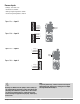
• Operating temperature: 0 to
80° C
• Contact type: normally open
• Maximum current: 8 amps
• Maximum voltage: 250VÅ
(ac)
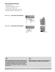
High-voltage Control Outputs
The state of each high-voltage control output mirrors the state of the corresponding control output.
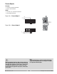
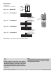
High Voltage Module
High-voltage
Control Outputs 1 to 3
1
2
3
4
5
6
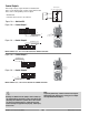
High Voltage Module
High-voltage Control Output 4
High-voltage Event Outputs 5 & 6
1
2
3
4
5
6