
Owner manual

Chapter 2: Install and Wire ■ 14 ■ Watlow Series N7
Ó
Warning: Use National Electric (NEC) or other country-spe-
cific standard wiring and safety practices when wiring and
connecting this controller to a power source and to electri-
cal sensors or peripheral devices. Failure to do so may
result in damage to equipment and property, and/or injury
or loss of life.
Note:
To prevent ground loops, maintain isolation from input to
output when using switched dc or analog process outputs.
Use ungrounded thermocouples.
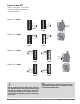
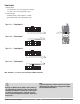
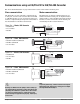
Figure 14b — Control Output 1
Figure 14c — Control Output 2
NOTE: Terminals 5, 6, 13 or 14 can be used for the common connection.
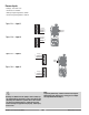
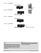
Figure 14d — Control Output 3
Figure 14e — Control Output 4
NOTE: Terminals 2, 5, 9 or 12 can be used for the common connection.
1
2
3 4567
891011 12
13
14
(common) 9
8
+
1
2
3 4567
891011 12
13
14
(common) 2
1
+
(common) 13
10
+
1
2
345678
91011
12
13
14
15
16
(common) 5
2
+
1
2
345678
91011
12
13
14
15
16
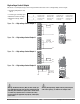
Internal Circuitry
dc-
dc+
5VÎ (dc) @ 30 mA (dc)
Load
Switched DC
+
+5VÎ (dc)
(common)
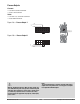
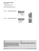
Control Outputs
If the high voltage output module is installed, the
state of each high-voltage control output mirrors the
state of the corresponding control output.
• Switched dc
• Current: 30 mA at 5VÎ (dc) nominal
Figure 14a — Switched DC
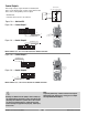
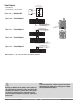
14 pins
Control Outputs 3 & 4
Process Outputs 1 & 2
Event Inputs 5 to 8
16 pins
Outputs 1 & 2
Event Inputs 1 to 4
Event Outputs 1 to 4
1
2
3
4
5
6