Series N7 Installation Manual Time and Temperature Controller TOTAL CUS CUSTOMER ER SATISF TISFACTI CTION 3 Year Warranty ISO 9001 Registered Company Winona, Minnesota USA 1241 Bundy Boulevard., Winona, Minnesota USA 55987 Phone: +1 (507) 454-5300, Fax: +1 (507) 452-4507 http://www.watlow.com 0600-0042-0000 Rev. B March 2004 Made in the U.S.A. $15.
Safety Information ç CAUTION or WARNING Ó Electrical Shock Hazard CAUTION or WARNING We use note, caution and warning symbols throughout this book to draw your attention to important operational and safety information. A “NOTE” marks a short message to alert you to an important detail. A “CAUTION” safety alert appears with information that is important for protecting your equipment and performance. Be especially careful to read and follow all cautions that apply to your application.
TC Table of Contents Chapter 1: Overview . . . . . . . . . . . . . . . . . . . . . . . . . . . . . . . . . . .4 Chapter 2: Install and Wire . . . . . . . . . . . . . . . . . . . . . . . . . . . . . .5 Dimensions . . . . . . . . . . . . . . . . . . . . . . . . . . . . . . . . . . . . . . . . .5 Wiring . . . . . . . . . . . . . . . . . . . . . . . . . . . . . . . . . . . . . . . . . . . . .9 Appendix . . . . . . . . . . . . . . . . . . . . . . . . . . . . . . . . . . . . . . . . . . . .21 Specifications . .
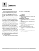
1 Overview Series N7 Controller Watlow’s Series N7 temperature controller provides ample flexibility for use in a broad range of applications. The Series N7 delivers up to four zones of on-off or PID control, that can be sensed with thermocouples (types J, K and E), 2-wire RTDs and 3wire RTDs. Voltage or process inputs are also available. The Series N7 offers a wide variety of outputs. The base model has six switched dc outputs, with a nominal output voltage of 5V and a maximum current of 30 mA.
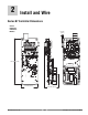
2 Install and Wire Series N7 Controller Dimensions Vertical Dimensions with Add-on Modules 6.15 mm (0.24 in) 197.74 mm (7.79 in) 72.14 mm (2.84 in) Watlow Series N7 61.10 mm (2.
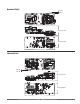
Vertical View with Add-on Modules (exploded view) Ethernet Add-on Module (see Appendix for details) (4) Nylon Spacers (3/16 X 5/16 X 1/16) Press spacer onto standoff clips prior to mounting Relay/High-Voltage Output Add-on Module (see Appendix for details) Chapter 2: Install and Wire ■ 6 ■ Watlow Series N7
Horizontal Right 6.15 mm (0.24 in) 61.10 mm (2.41 in) 72.14 mm (2.84 in) 197.74 mm (7.79 in) Horizontal Left 6.15 mm (0.24 in) 61.10 mm (2.41 in) 72.14 mm (2.84 in) 197.74 mm (7.
Cutout Standoff -Vertical For Horizontal Left, rotate 90° counter-clockwise. For Horizontal Right, rotate 90° clockwise. 4X 60.96 mm (2.400 in) 54.91 mm (2.162 in) 31.75 mm (1.25 in) CL 2X 12.71 mm (.500 in) 2X 24.03 mm (.946 in) 71.12 mm (2.800 in) 2X 60.96 mm (2.400 in) 4X 45˚ 2X 123.63 mm (4.867 in) 2X 186.57 mm (7.345 in) 4X Blind #4-40 X .31 in threaded standoff, Pem BSOS-6440-10 or equivalent. (4X #4-40 X .75 in long machined screw required) 4X Blind #4-40 X .
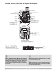
Location of Pins and Ports for Inputs and Outputs 5-pin Master Communications Port 9-pin Slave Communications Port Input 3 Input 4 6 5 4 3 2 1 1 2 3 4 5 6 Input 2 Input 1 14 pins Control Outputs 3 & 4 Process Outputs 1 & 2 Event Inputs 5 to 8 16 pins Power Control Outputs 1 & 2 Event Inputs 1 to 4 Event Outputs 1 to 4 High Voltage Module High-voltage Control Outputs 1 to 3 High Voltage Module High-voltage Control Outputs 4 High-voltage Event Outputs 5 & 6 Figure 9a — Power Wiring • Nominal voltage
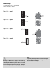
Thermocouple • J and K: –46 to 316°C (–50 to 600°F) Input 2 Input 1 5 1 2 3 + 4 – 5 4 6 2 6 5 4 3 2 1 1 2 3 4 5 6 + 1 – Figure 10b — Input 2 2 1 3 4 5 Figure 10a — Input 1 6 • Input impedance: >100 kΩ + – 2 1 2 1 Figure 10c — Input 3 3 4 5 6 1 2 3 4 5 6 1 Figure 10d — Input 4 Input 3 Input 4 2 3 5 – 4 5 4 + 6 Ó Warning: Use National Electric (NEC) or other country-specific standard wiring and safety practices when wiring and connecting this controller to a power sou
2-wire or 3-wire RTD • 100 Ω : –46 to 316°C (–50 to 600°F) • DIN curve: 0.
Process Inputs • Voltage: 0 to 10VÎ (dc) • Current: 0 to 20 mA • Voltage input impedance: 50 kΩ 6 6 Common 5 5 Current – + 4 Voltage + Input 2 Input 1 6 5 4 3 2 1 1 2 3 4 5 6 1 2 3 Figure 12b — Input 2 3 Common – 2 Current + 1 Voltage + 4 1 2 3 4 5 Figure 12a — Input 1 6 • Current input impedance: 100 Ω Voltage 1 Current 2 2 – Common 3 3 + + 1 Figure 12c — Input 3 4 5 Input 3 Input 4 1 2 3 4 5 6 6 1 Figure 12d — Input 4 2 3 Ó Warning: Use National Electric (NEC) or othe
Process Outputs Current • 0 to 20 mA at 20V maximum • Load: 1 kΩ maximum Volts • 0 to 10VÎ (dc) at 20 mA maximum • Load: 500Ω minimum Figure 13a — Process Output 1 – + 4 3 1 2 3 8 9 10 1 2 3 8 9 10 6 7 11 12 13 4 5 14 14 pins Control Outputs 3 & 4 Process Outputs 1 & 2 Event Inputs 5 to 8 Figure 13b — Process Output 2 + – 5 6 7 11 12 13 14 10 11 Ó Warning: Use National Electric (NEC) or other country-specific standard wiring and safety practices when wiring and connecting this
Control Outputs Switched DC 5VÎ (dc) @ 30 mA (dc) If the high voltage output module is installed, the state of each high-voltage control output mirrors the state of the corresponding control output.
High-voltage Control Outputs The state of each high-voltage control output mirrors the state of the corresponding control output.
Event Inputs • Voltage input –0.5 to +0.
Figure 17a — Event Input 5 6 + – (common) 5 1 2 3 8 9 10 6 7 11 12 13 4 5 14 14 pins Control Outputs 3 & 4 Process Outputs 1 & 2 Event Inputs 5 to 8 Figure 17b — Event Input 6 1 2 3 8 9 10 6 7 11 12 13 4 5 14 – (common) 12 + 13 Figure 17c — Event Input 7 + 7 – (common) 5 1 2 3 8 9 4 5 6 7 10 11 12 13 14 1 2 3 6 7 8 9 10 11 12 13 14 Figure 17d — Event Input 8 4 5 Note: Terminals 2, 5, 9 or 12 can be used for the common connection.
Event Outputs Switched DC 5VÎ (dc) @ 30 mA (dc) • Switched dc • 30 mA at 5VÎ (dc) nominal +5VÎ (dc) dc+ + Load Figure 18a — Switched DC dc(common) Internal Circuitry Figure 18b — Event Output 1 16 15 8 7 14 13 12 11 10 9 6 3 2 1 5 4 3 – + (common) 5 8 14 13 12 11 10 9 7 6 3 2 1 16 15 14 13 12 11 10 9 8 7 6 3 2 1 5 4 5 4 4 (common) 5 (common) 13 Figure 18e — Event Output 4 12 16 15 8 7 14 13 12 11 10 9 6 3 2 1 5 4 + – Figure 18d — Event Out
High-voltage Event Outputs • Solid-state relay • Operating temperature: 0 to 80° C • Contact type: normally open • Maximum operating current: 0.
Communications using an EIA/TIA-232 to EIA/TIA-485 Converter The circuit board illustration on page 9 shows the location of the master and slave ports. Slave communications Master communications The Series N7 can only respond to communications on this port, as in the case of several N7s networked to a Modbus master or a PC connected to this port to monitor or adjust settings and process values. This is how most Watlow controllers communicate.
A Appendix Specifications Controller • • • • • • Up to four sensor inputs, eight switched dc outputs, eight dc inputs, two process outputs Battery backed, real-time clock One non-isolated slave communications channel One non-isolated master communications channel Optional ethernet communications module Optional high-voltage output module • • • • Current Input impedance 100 Ω Input range: 0 to 22mA Accuracy: ± 40 µA Drift: ± 5 µA/F • • Event Input Input high: 3 to 30V or >10 kΩ Input low: -0.5 to 0.
SSR Specification Contact type: normally open Maximum operating current: 0.4 A Maximum operating voltage: 250VÅ (ac) Pilot duty: 100 VA No Arc Specification Contact type: normally open Maximum operating current: 8 A Maximum operating voltage: 250VÅ (ac) Note: These specifications are subject to change without prior notice. High-Voltage Modules Ordering Information • A007-2660-0000 - 2 solid-state relays (0.4 A) • A007-2660-0001 - 2 solid-state relays (0.
Ordering Information and Model Numbers _N_ _7_ _ _ _ _ - _ _ _ _ _ _ _ _ - _ _ _ _ _ _ _ _ Customer Name Inputs 1 & 2 1 2 3 4 5 6 Input Input Input Input Input Input 1 1 1 1 1 1 & Input 2 thermocouple thermocouple, Input 2 process thermocouple, Input 2 RTD & Input 2 process RTD, Input 2 process & Input 2 RTD Inputs 3 & 4 0 1 2 3 4 5 6 none Input Input Input Input Input Input 3 3 3 3 3 3 & Input 4 thermocouple process, Input 4 thermocouple RTD, Input 4 thermocouple & Input 4 process RTD, Input 4 proc
Install or Replace the Relay/High Voltage Output Module (Z100-0817-000X) 1. Remove power from the controller. 2. Pre-assemble the circuit board spacers onto the Relay/High Voltage Output circuit board. • Insert the pointed end of a circuit board spacer into one of the four mounting holes of the Relay/High Voltage Output circuit board from the side of the circuit board that has the output terminal blocks.
Install or Replace the Ethernet Module (Z100-0816-0000) 1. Remove power from the controller. 2. Pre-assemble the circuit board spacers onto the Ethernet circuit board. • Insert the pointed end of a circuit board spacer into one of the four mounting holes of the Ethernet circuit board from the side of the circuit board that has the label on it. • Using firm pressure seat the circuit board spacer until the head of the spacer is flush with the surface of the Ethernet circuit board.
Notes: Appendix ■ 26 ■ Watlow Series N7
Declaration of Conformity Series N7 Watlow Winona, Inc. 1241 Bundy Blvd.
How to Reach Us Your Authorized Watlow Distributor: TOTAL CUS CUSTOMER ER SATISF TISFACTI CTION 3 Year Warranty Corporate Headquarters in the U.S.: Watlow Electric Manufacturing Co. 12001 Lackland Road St. Louis, Missouri, USA 63146 Telephone: +1 (314) 878-4600 Fax: +1 (314) 878-6814 Europe: Watlow GmbH Industriegebiet Heidig Lauchwasenstr. 1, Postfach 1165 Kronau 76709 Germany Telephone: +49 (0) 7253-9400 0 Fax: +49 (0) 7253-9400-44 Watlow France S.A.R.L.