
User Manual


Watlow Series F4S/D Wiring ■ 12.5
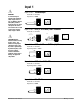
Inputs x (2 and 3) (continued)
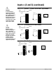
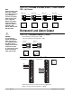
Figure 12.5a — 0 to 5VÎ, 1 to 5VÎ or 0 to 10VÎ (dc) Process
F4S _ - _ _ _ 6 - _ _ _ _ or F4D _ - _ _ _ _ - _ _ _ _
Input impedance: 20kΩ
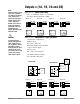
Figure 12.5b — 0 to 20mA or 4 to 20mA Process
F4S _ - _ _ _ 6 - _ _ _ _ or F4D _ - _ _ _ _ - _ _ _ _
Input impedance: 100Ω
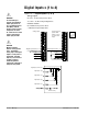
Figure 12.5c — 0 to 50mV
F4S _ - _ _ _ 6 - _ _ _ _ or F4D _ - _ _ _ _ - _ _ _ _
Impedance: 20MΩ
+57
-58
51 52 53 54 55 56 57 58
+55
-56
51 52 53 54 55 56 57 58
Input 2 Input 3
1 2 3 4 5
6 7 8 9 10 11 12 13 14
1 2 3 4 5 6 7 8 9 10 11 12 13 14
15 16
15 16
17 18 19 20 21 22 23 24
25 26
27 28 29 30 31 32
17 18 19 20 21 22 23 24 25 26 27 28 29 30 31 32
59 60 61 62
48 49 50
45 46 47
45 46 47
51 52 53 54 55 56 57 58
51 52 53 54 55 56 57 58
33 34 35
33 34 35
36 37 38
36 37 38
39 40 41
39 40 41
42 43 44
42 43 44
51 52 53 54 55 56 57 58
+54
-58
51 52 53 54 55 56 57 58
+52
-56
Input 2 Input 3
1 2 3 4 5 6 7 8
9 10 11 12 13 14
1 2 3 4 5 6 7 8 9 10 11 12 13 14
15 16
15 16
17 18 19
20 21 22
23 24 25 26 27 28
29 30 31
32
17 18 19 20 21 22 23 24 25 26 27 28 29 30 31 32
59 60 61 62
59 60 61 62
48 49 50
48 49 50
45 46 47
45 46 47
51 52 53 54 5
5 56 57 58
51 52 53 54 55 56 57 58
33 34 35
33 34 35
36 37 38
36 37 38
39 40 41
42 43 44
42 43 44
51 52 53 54 55 56 57 58
+53
-58
51 52 53 54 55 56 57 58
+51
-56
Input 2
Input 3
1 2 3 4 5 6 7
8 9 10 11 12 13 14
1 2 3 4 5 6 7 8 9 10 11 12 13 14
15 16
15 16
17 18 19 20 21 22 23 24 25 26 27 28
29 30 31 32
17 18 19 20 21 22 23 24 25 26 27 28 29 30 31 32
59 60 61 62
59 60 61 62
48 49 50
48 49 50
45 46 47
45 46 47
51 52 53 54 5
5 56 5
7 58
51 52 53 54 55 56 57 58
33 34 35
33 34 35
36 37 38
36 37 38
39 40 41
39 40 41
42 43 44
42 43 44
ç
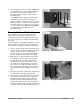
WARNING:
To avoid damage to
property and equipment,
and/or injury of loss of
life, use National Electric
Code (NEC) standard
wiring practices to install
and operate the Series
F4. Failure to do so could
result in such damage,
and/or injury or death.
ç
CAUTION:
Maintain isolation
between analog inputs 2
and 3, and between
analog input 1 and digital
inputs 1 to 4 to prevent a
ground loop. A ground
loop may cause incorrect
readings. Failure to
follow this guideline
could result in damage to
equipment and product.