
Owner manual


Watlow Controls 7 EHG CL User’s Guide
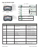
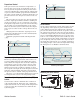
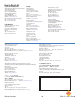
Wiring the Series EHG CL Power, Thermocouple and
Heater Connections
View looking at the top of the controller.
L1
(
black
)
L2
(
white
)
1
3
4
5
7
8
6
2
L1
(black)
L2
(white)
Power and relay connectors
6.0” +/-0.5” relaxed length
>= 18” extended length
3.5” +/- 0.5”
Control Power Cord Coiled, Terminated Long
Part Number: 4800-0022
3.5” +/- 0.5”
12.0” +/- 1” Relaxed Length
>= 36” Extended Length
Control Power Cord Coiled, Jumpered Long
Part Number: 4800-0012
Control Power Cord Coiled, Jumpered Short
Part Number: 4800-0011
3.5” +/- 0.5”
7.0” +/- 1” Relaxed Length
3.5” +/- 0.5”
3.5” +/- 0.5”
Relaxed Length
Control Power Cord Coiled, Terminated Short
Part Number: 4800-0021
With the control facing you this connector is on the
right side.
L1
Switched
(black)
L2
(white)
+ (yellow)
– (red)
+ (yellow)
– (red)
1
3
4
5
7
8
6
2
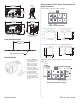
Heater
Limit
Thermocouple
Process
Thermo-
couple
Thermocouple and heater connector
81.5 mm
(3.210 in)
48.4 mm
(1.905 in)
Interface
front
24.7 mm
(0.974 in)
Interface
side
88.8 mm
(3.496 in)
55.8 mm
(2.196 in)
Base Controller with Interface
front
63.6 mm
(2.503 in)
Base Controller with
Interface side
Panel Mount Dimensions
45.72 mm
(1.800 in)
drill and tap for #8-32
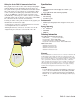
Mounting Bracket
The Series EHG CL
mounting bracket lets
you mount the con-
troller in any of four
angles. After discon-
necting both wiring
connectors, gently
rotate the controller
counterclockwise until
it unlocks from the
mounting bracket.
Re-orient the control-
ler on the mounting
bracket and gently ro-
tate it clockwise until
it locks.