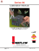
Series 96 Calibration Manual 1/16 DIN Temperature Controller with Custom Toolbar (patent pending) 97 TOTAL CUSTOMER CUST SATISF TISFA ACTI CTIO ON 3 Year Warranty ISO 9001 Registered Company Winona, Minnesota USA Watlow Controls 1241 Bundy Blvd., P.O. Box 5580, Winona, Minnesota USA 55987-5580 Phone: (507) 454-5300, Fax: (507) 452-4507 http://www.watlow.com January 1999 (1627) Made in the U.S.A.
Table of Contents Calibrating the Series 96.......................................................3 Thermocouple Input Procedure.............................................4 Voltage Process Input Procedure .........................................5 Current Process Input Procedure .........................................5 Process Output Procedures ..................................................6 Calibration Parameters .........................................................8 Ordering Information ......
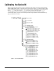
Calibrating the Series 96 Warm up the unit (20 minutes). To enter a calibration menu, enter the Factory Page by holding down the ˆ and ‰ keys for six seconds. Once in the Factory Page [Fcty] use the Up-arrow ¿ or Down-arrow ¯ Key to select a menu. The last three menus on the Factory Page are Calibration 1 Menu [cin1], Calibration 2 Menu [cin2] and Process Output Calibration Menu [cout].
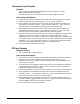
Thermocouple Input Procedure Equipment • Type J reference compensator with reference junction at 32°F/0°C, or type J thermocouple calibrator to 32°F/0°C. • Precision millivolt source, 0 to 50mV minimum range, 0.002mV resolution. Input 1 Setup and Calibration 1. Connect the correct power supply to terminals 8 and 9 (see Series 96 User’s Manual). 2. Connect the millivolt source to terminals 6 (-) and 7 (+) with copper wire. 3. Enter 50.000mV from the millivolt source.
Voltage Process Input Procedure Equipment • Precision voltage source, 0 to 10V minimum range, with 0.001V resolution. Input 1 and 2 Setup and Calibration 1. Connect the correct power supply to terminals 8 and 9 (see Series 96 User’s Manual). Input 1 2. Connect the voltage source to terminals 4 (+) and 6 (-) of the controller. 3. Enter 0.00V from the voltage source to the controller. Allow at least 10 seconds to stabilize. Set Process Calibration 1, 0V [A`0u] (Calibration 1 Menu) to [`yES].
Process Output Procedures Equipment • Precision volt/ammeter with 3.5-digit resolution. Output 1 Setup and Calibration 1. Connect the correct power supply to terminals 8 and 9 (see Series 96 User’s Manual). Milliamperes 2. Connect the volt/ammeter (set to milliamperes) to terminals 13 (+) and 14 (-). 3. At Output Calibration 1, 4mA [1``4] (Process Output Calibration Menu) enter the reading from the ammeter. The unit should stabilize within one second. Repeat until the ammeter reads 4.00mA, ±0.1mA.
Output 4 Setup and Calibration 1. Connect the correct power supply to terminals 8 and 9 (see Series 96 User’s Manual). Milliamperes 2. Connect the volt/ammeter (set to milliamperes) to terminals 20 (-) and 21 (+). 3. At Output Calibration 4, 4mA [4``4] (Process Output Calibration Menu) enter the reading from the ammeter. The unit should stabilize within one second. Repeat until the ammeter reads 4.00mA, ±0.1mA. Press the Advance Key ‰ to store the value and move to the next prompt. 4.
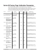
Series 96 Factory Page Calibration Parameters The resting-state display shows one of the following sets of data, depending on controller setup. The first prompt appears in the top display, the second in the bottom. To enter the calibration mode, first enter the diagnostics mode; send value 1789 to register 1512. Once in Diagnostics mode, to enter calibration mode, send 1415 to register 1600. To restore factory calibration settings, send value 1 to register 1601.
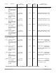
Display Parameter Range (Modbus Value) Default Modbus Address Read/Write Conditions for Parameters to Appear [``no] no (0) [`yes] yes (7) [``no] (0) 1603 w Active if Calibration Lock (Lockout Menu) is not set to [hide]. [``no] no (0) [`yes] yes (8) [``no] (0) 1603 w Active if Calibration Lock (Lockout Menu) is not set to [hide]. [``no] no (0) [`yes] yes (9) [``no] (0) 1603 w Active if Calibration Lock (Lockout Menu) is not set to [hide].
Display Parameter Range (Modbus Value) Default Modbus Address Read/Write Conditions for Parameters to Appear [cout] Process Output Calibration Menu [Fcty] Factory Page [1``4] Output Calibration 1, 4mA 0.00 to 99.99 4.00 (400) 1604 w Active if output 1 is process (96 _ _-F _ _ _-_ _ _ _) and Calibration Lock (Lockout Menu) is not set to [hide]. 0.00 to 99.99 20.00 (2000) 1605 w Active if output 1 is process (96 _ _-F _ _ _-_ _ _ _) and Calibration Lock (Lockout Menu) is not set to [hide]. 0.
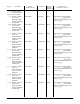
Display Parameter [4`20] Output Calibration 4, 20mA Range (Modbus Value) Default Modbus Address Read/Write 0.00 to 99.99 20.00 (2000) 1620 w Active if output 4 is process (96 _ _- _ _ _ M -_ _ _ _) and Calibration Lock (Lockout Menu) is not set to [hide]. 0.00 to 99.99 1.00 (100) 1621 w Active if output 4 is process (96 _ _- _ _ _ M -_ _ _ _) and Calibration Lock (Lockout Menu) is not set to [hide]. 0.00 to 99.99 10.
How to Reach Us Contact TOTAL • Phone: (507) 454-5300. CUSTOMER SATISFACTION 3 Year Warranty • Fax: (507) 452-4507. • For technical support, ask for an Applications Engineer (ext. 1111). • To place an order, ask for Customer Service. • To discuss a custom option, ask for a Series 96 Product Manager.