How To Use Data Communications with the Watlow Series 945 User's Manual Watlow Controls, 1241 Bundy Blvd., P.O.Box 5580, Winona, MN 55987-5580, Phone: 507/454-5300, Fax: 507/452-4507 W945-SA50-9210 March, 1992 Supersedes: W945-SA40-9119 How to Use Data Communications $5.00 Made in the U.S.A.
Contents Page 3 3 3 4 5 6 6 7 7 7 8 10 11 11 11 12 12 13 13 14 15 16 16 16 17 17 18 19 20 22 23 23 24 25 26 26 27 2 Item Data Communications and the Series 945 Hardware Interfaces Protocols Communications Wiring RS-422A Interface Pinouts RS-423A Interface Pinouts (RS-232C Compatible) EIA-485 Interface Pinouts Connecting the Control and Computer Setting Hardware Protocol Switches Network Connections Series 945 Communication Parameters Communications Setup Parameters ASCII and Series 945 Information Series
Data Comm How to Use Data Communications with the Watlow Series 945 This manual is a supplement to the Series 945 User's Manual. It is for users with the data communications option. Use in conjunction with the Series 945 User's Manual. This is expert user-level material and requires previous experience with data communications.
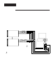
RS-422A RS-422A Interface Pinouts 945A-XXXX-B000 The RS-422A communications uses a four wire (full duplex) system. There are two separate lines for transmitting, and two lines for receiving data between the computer and the Series 945. With RS-422A you can have from one to ten Series 945 controls connected to a single computer. This diagram is a typical wiring example. The connections on the host computer may vary depending on models. Refer to your computer user's manual for more information.
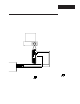
RS-423A RS-423A Interface Pinouts (RS-232C Compatible) 945A-XXXX-B000 The RS-423A communications uses a three wire (full duplex) system. There is a separate line for transmitting, a line for receiving data, and a line for signal common between the computer and the Series 945. With RS-423A you can have only one Series 945 control connected to a single computer or printer. This diagram is a typical wiring example. The connections on the host computer may vary depending on models.
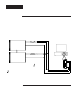
EIA-485 EIA-485 Interface Pinouts 945A-XXXX-D000 The EIA-485 communications uses a two wire (half duplex) system. There are only two lines, both lines used for transmitting and receiving. Only one device, the computer or the control, can be speaking at a time. There is a 1 millisecond delay requried for the Series 945 to go between transmission and receipt of data. With EIA-485 you can have from one to thirty-two Series 945 controls connected to a computer. Figure 3 EIA-485 Interface, Pin Designations.
Configuration (Up) (Up) RS-423A RS-423A Figure 4 RS-422A/RS-423A Switch Selection. (Down) RS-422A (Down) RS-422A A007-1830 NOTE: The Series 945 leaves the factory in RS-423A operation (C1). How to Set the Hardware Protocol Switches for 945A-XXXX-B000 Units Only The RS-422/RS-423 switches are on the Communication Module Board (A0071830). Figure 4 shows the location of this board. You can select C1 for RS-423 or C2 for RS-422 operation. Both switches must be set the same for the desired protocol.
Parameters Setup Menu - Communications Parameters Enter the Setup menu by pressing the UP/DOWN keys simultaneously for 3 seconds. The lower display shows the LOC parameter, and the upper display shows its current level. All keys are inactive until you release both keys. You can reach the LOC parameter from anywhere. This is only a listing and brief explanation of the parameters, refer to Pages 22 through 26 for a thorough explanation of Statistical Process Control (SPC).
Minutes: Represents the 24 hour time-of-day clock setting for minutes. Appears if Prot = On and Log = tAbL, CHrt or SPCA, SPCd, SPCn. Parameter resets to default after a power interruption. Range: 0 to 59 Default: 0 Setup Interval: Selects the time interval for the logging function. The logging interval is in tenth of a minute increments. Appears if Prot = On and Log = tAbL, CHrt or SPCA, SPCd, SPCn. Range: 0.0 to 60.0 minutes Default: 0.
ASCII Char.
Syntax Series 945 General Message Syntax As soon as you link the devices, you'll be able to talk to the Series 945 using ASCII characters. The Series 945 will respond to any Operating or Setup parameter, plus some others. The control will respond to either upper or lower case ASCII characters from your computer. Both protocol/interface combinations will respond to the general syntax, providing the commands or queries are correctly transmitted. However, the ANSI X3.
ASCII Example Format For your benefit, we're presenting message/response examples with syntax required for Series 945 communication. Information bracketed by < > indicates a description, rather than literal characters. We show each ASCII character that you must transmit to the Series 945, including space between the characters. (A "space" is itself an ASCII character, hex 20). For clarity, we also represent each ASCII character as a hexadecimal pair. The pairs are spread apart on the page for easy reading.
XON/XOFF "=" How To Start and Stop Communicating with the Series 945 and XON/XOFF Starting communications with XON/XOFF Protocol is simple. You just configure your computer to agree with the Series 945 communication parameters and open its serial communication port in software. Then begin to "talk" by transmitting a message to the Series 945. You stop communicating with XON/XOFF Protocol simply by ceasing to send messages.
XON/XOFF "?" XON/XOFF "?" Command Example You want to know the Alarm 1 Low (A1LO) value. The "?" uses a variation of the message syntax shown just below. This protocol requires an ending carriage return character. "?" Command syntax with XON/XOFF Protocol: ? Data.1 Enter in ASCII: ? A1LO The hex string will be: 3F2041314C4F0D ? Space A Figure 7 XON/XOFF "?" Command Example.
ANSI X3.28 ANSI X3.28 Protocol for RS-422A and EIA-485 The ANSI X3.28 Protocol provides high quality communications by requiring a response to every message. With a multiple device or "multidrop" network, this protocol prevents confusion among the separate devices. Furthermore, if noise occurs somewhere in the system, no parameter will change because noise can't comply with the protocol. By placing messages inside a protocol envelope, the messages are protected.
ANSI X3.28 "=" Stopping Communications in ANSI X3.28 Protocol The master device, your computer, must end communications with Device #4 by using Data Link Escape (DLE) and End of Transmission (EOT) characters. Enter in ASCII: ASCII Characters HEX Value 10 04 Response from the 945: None ANSI X3.28 "=" Command Example The "=" Command sets a specific 945 parameter to a specific value. The general command syntax applies to all commands.
ANSI X3.28 "?" Response from the Series 945: The hex response string is: 06 • You'll find the the complete list of "=" command arguments (parameters and value limits) in Table 6, Pages 20 - 21. ANSI X3.28 "?" Command Example You need to know the Alarm 1 Low value (A1LO). The "?" uses a variation of the message syntax shown just below. This syntax requires the protocol start of text and end of text characters. "?" command syntax with ANSI X3.28 Protocol: ?
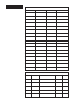
Commands Data.1 Respns Information Comments Actual process value Between R1L and R1H C1 ACTUAL IN 0 1 2 3 4 5 6 7 8 9 10 11 12 13 J T/C K T/C T T/C N T/C PT2 T/C C T/C Not Used R T/C S T/C B T/C RTD whole RTD tenths 0-5V 4-20mA MODE 1 2 4 8 16 Auto mode Manual mode Configuration mode Calibration mode Alarm silence active Multiple modes are possible.
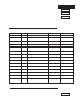
Commands "=" Command "The "=" Command sets a specific Series 945 parameter (Data.1) to a specific value (Data.2) when the unit is in the HOLD mode. Use Tables 5 and 6 to select parameters (Data.1) in the lefthand column. In Table 6 the low and high limit or code values (Data.2) are in the three center columns. Data.1 AXHI AXLO ALM AL1 Data.
Commands Data.1 Data.2 Low Limit NOTE: An X means it applies to either Output 1 or Output 2. LATX 0 1 LINE LOC LOG 10 0 0 127 3 3 0 1 L-R LSL MAN MIN MON OTX Table 6 Continued High Limit rL USL Lower -2°F/-1°C -100 100 0 59 1 12 0 1 or 2* OT4 0 2 PBX 0 0.0 999°F 555°C 999 Units 999.9 RAX REX RH RL RSP 0.00 0.00 Min. IN range Min. IN range 0 9.99 9.99 Max. IN range Max.
Data Logging Data Logging The data logging feature is a convenient replacement for chart recorders. Information is sent directly from the Series 945 to a serial printer, or to a computer disk file. No computer is needed, although the 945 can be connected to a computer with a serial port and terminal emulation software. Data logging provides a handy reference to review process performance.
Data Logging Data fields emitted are determined by the tag parameters and control configuration. As in the following example, tag is set for PSA (Process, Set Points, and Alarm Set Points). SET-2 is only transmitted when there is a secondary control output, and is configured the same as the primary output. In the example below, notice A1LO was changed to 125 resulting in an alarm condition shown as an * (asterisk) in the PROCESS and LOW-1 columns.
SPC The Difference Between Control & Specification Limits Control limits are established on the control chart at ± 3 standard deviations (3 sigma). They are based upon the distribution of sample averages and are calculated from the actual performance of the process. They are typically narrower than specification limits. Specifications are limits for individual measurements, not averages. They are based upon engineering or customer requirements, rather than process capability.
Chart & SPC Chart and SPC Printout Example: Log = SPCA, Int = 0.1 P = Process S = Set Points Set Point DATE: 01-01-90 PROCESS 75 * 01:00:01 NOTE: The time is printed every 5th interval (Int). The temperature variable (*) is printed every 10th interval. One Int = 6 seconds. * * * * * Temperature Variable 01:00:31 01:01:01 01:01:31 Lower Control Limit (SPCA & SPCd only) 01:02:01 Figure 12 Chart and SPC Printout Example 125 100°F Temperature CPKL = 1.
Error Codes Problem Cause Action Printing all on the same line. The line feed is missing. Set the printer for a carriage return and line feed. The printing is garbled. Data formats are not compatible. Match the Series 945 data format to the printers data format using the "Data" prompt. The printer will not print. The printer is off line. Bring the printer on line. The transmit and receive lines are reversed.
Index A ALM, 20 ANSI X3.28 "=" Command, Fig. 8, 17 ANSI X3.28 "?" Command, Fig. 9, 18 ANSI X3.
Notes How to Use Data Communications WATLOW Series 945 27
Series 945 Data Communications User's Manual Watlow Controls, 1241 Bundy Blvd.