Series 942 How To Use Data Communications with the Watlow Series 942 TOTAL CUSTOMER SATISFACTION Watlow Controls 1241 Bundy Blvd., P.O. Box 5580, Winona, MN 55987-5580, Phone: 507/454-5300, Fax: 507/452-4507 W942-XDCN-Rev.T00 August, 1995 Supersedes: W942-SA20-9312 $10.00 Made in the U.S.A.
Contents Page 3 3 3 4 5 6 7 7 8 8 8 8 10 10 10 11 11 12 12 13 14 15 15 15 16 16 17 18 19 21 21 22 22 22 23 23 23 25 25 26 2 Item Data Communications and the Series 942 Hardware Interfaces Protocols Communications Wiring RS-422A Interface Pinouts RS-423A Interface Pinouts (RS-232C Compatible) EIA-485 Interface Pinouts Setting Hardware Protocol Switches Network Connections Connecting the Control and Computer Communications Parameters ASCII and Series 942 Information Communication Software Series 942 General
How to Use Data Communications with the Watlow Series 942 Data Comm This manual is a supplement to the Series 942 User's Manual. It is for users with the data communications option. Use in conjunction with the Series 942 User's Manual. This is expert user-level material and requires previous experience with data communications.
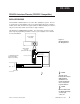
RS-422A RS-422A Interface Pinouts 942A-XXXX-B000 The RS-422A communications uses a four wire (full duplex) system. There are two separate lines for transmitting, and two lines for receiving data between the computer and the Series 942. With RS-422A you can have from one to ten Series 942 controls connected to a single computer. This diagram is a typical wiring example. The connections on the host computer may vary depending on models. Refer to your computer user's manual for more information.
RS-423A RS-423A Interface Pinouts (RS-232C Compatible) 942A-XXXX-B000 The RS-423A communications uses a three wire (full duplex) system. There is a separate line for transmitting, a line for receiving data between the computer and the Series 942, and a line for signal common. With RS-423A you can have only one Series 942 control connected to a single computer. This diagram is a typical wiring example. The connections on the host computer may vary depending on models.
EIA-485 EIA-485 Interface Pinouts 942A-XXXX-D000 The EIA-485 communications uses a two wire (half duplex) system. There are only two lines, both lines used for transmitting and receiving. Only one device, the computer or the control, can be speaking at a time. There is a 5 millisecond delay required for the Series 942 to go between transmission and receipt of data. With EIA-485 you can have from one to thirty-one Series 942 controls connected to a computer. This diagram is a typical wiring example.
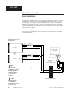
Configuration (Up) RS-423A RS-423A (Up) (Down) RS-422A (Down) RS-422A Figure 4 RS-422A/RS-423A Switch Selection. NOTE: The Series 942 leaves the factory in RS-423A operation (C1). Control Chassis - Top View How to Set the Hardware Protocol Switches for 942A-XXXX-B000 Units Only The RS-422/RS-423 switches are on the Communication Module Board (A007-1830). Figure 4 shows the location of this board. You can select both C1 switches for RS-423 or both C2 switches for RS-422 operation.
Comm Software Connecting the Control and the Computer Remove power from both the Series 942 and your computer before connecting them together. This prevents noise or static interference from entering the data communication lines. Assemble a cable and the appropriate wiring at your computer. Refer to the wiring on Page 4 through 6. As soon as you connect the data communications line(s), you're ready to apply power to your system.
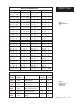
ASCII Char. ASCII Character Set Dec 00 01 02 03 04 05 06 07 08 09 10 11 12 13 14 15 Hex 00 01 02 03 04 05 06 07 08 09 0A 0B 0C 0D 0E 0F Char NUL SOH STX ETX EOT ENQ ACK BEL BS HT LF VT FF CR SO SI Dec 16 17 18 19 20 21 22 23 24 25 26 27 28 29 30 31 Hex 10 11 12 13 14 15 16 17 18 19 1A 1B 1C 1D 1E 1F Char DLE DC1 DC2 DC3 DC4 NAK SYN ETB CAN EM SUB ESC FS GS RS US Dec 32 33 34 35 36 37 38 39 40 41 42 43 44 45 46 47 Hex 20 21 22 23 24 25 26 27 28 29 2A 2B 2C 2D 2E 2F Char SP ! " # $ % & ' ( ) * + , .
Syntax Series 945 General Message Syntax As soon as you link the devices, you'll be able to talk to the Series 942 using ASCII characters. The Series 942 will respond to any operating or set up parameter, plus some others. The control will respond to either upper or lower case ASCII characters from your computer. Both protocol/interface combinations will respond to the general syntax, providing the commands or queries are correctly transmitted. However, the ANSI X3.
ASCII Command List These commands, represented by their respective ASCII characters, will enable you to program the Series 942 from your computer. More detailed descriptions of the commands are on the pages noted. ? = Finds the value of a specific parameter. Sets a specific parameter to a specific value. p. 18 p. 19 Example Format For your benefit, we're presenting message/response examples with syntax required for Series 942 communication.
XON/XOFF To send the message on Page 11, Figure 5, you key the ASCII characters into your computer, or write them into your program. The computer, in turn, will send a string similar to the one at the bottom of the example, 3D2041314C4F20353030. Notice that we haven't mentioned protocol here, or any characters added to this syntax by a protocol. With XON/XOFF, the message above can be transmitted with only an additional Carriage Return (hex 0D) character at the end. However, the ANSI X3.
XON/XOFF "=" XON/XOFF "=" Command Example The general command syntax is the one you've already seen. Each command uses a slightly different variation of it, depending on the number of arguments required for a message. • You want to change the Alarm 1 Low (A1LO) value to 500°. The "=" Command will do the job. The syntax with XON/XOFF Protocol requires an ending Carriage Return . "=" Command Syntax with XON/XOFF Protocol: = Data.1 Data.2 With the "=" Command, Data.
XON/XOFF "?" XON/XOFF "?" Command Example You want to know the Alarm 1 Low (A1LO) value. The "?" uses a variation of the message syntax shown just below. This protocol requires an ending carriage return character. "?" Command syntax with XON/XOFF Protocol: ? Data.1 Enter in ASCII: ? A1LO The hex string will be: 3F2041314C4F0D ? Space A Figure 7 XON/XOFF "?" Command Example.
ANSI X3.28 ANSI X3.28 Protocol for RS-422A and EIA-485 The ANSI X3.28 Protocol provides high quality communications by requiring a response to every message. With a multiple device or "multidrop" network, this protocol prevents confusion among the separate devices. Furthermore, if noise occurs somewhere in the system, no parameter will change because noise can't comply with the protocol. By placing messages inside a protocol envelope, the messages are protected.
ANSI X3.28 "=" Stopping Communications in ANSI X3.28 Protocol The master device, your computer, must end communications with Device #4 by using Data Link Escape (DLE) and End of Transmission (EOT) characters. Enter in ASCII: ASCII Characters HEX Value 10 04 Response from the 942: None ANSI X3.28 "=" Command Example The "=" Command sets a specific 942 parameter to a specific value. The general command syntax applies to all commands.
Response from the Series 942: The hex response string is: 06 ANSI X3.28 "?" • You'll find the the complete list of "=" Command arguments (parameters and value limits) in Table 5, Pages 19 - 21. ANSI X3.28 "?" Command Example You need to know the Alarm 1 Low value (A1LO). The "?" uses a variation of the message syntax shown just below. This syntax requires the protocol start of text and end of text characters. "?" Command syntax with ANSI X3.28 Protocol: ?
Commands Data Comm "?" Command The "?" command finds the specific value of a Series 942 parameter (Data.1). Table 4 and 5 provide the complete list of parameters you may use, plus responses. You may use the "?" command in either the RUN or HOLD modes. Table 4 "?" Commands and Responses. These commands are READ ONLY. The "?" Command reads a specific value of the Series 942 parameter (Data.1). Data.
Commands "=" Command "The "=" command sets a specific Series 942 parameter (Data.1) to a specific value (Data.2) when the unit is in the HOLD mode. Use Tables 4 and 5 to select parameters (Data.1) in the lefthand column. In Table 5 the low and high limit or code values (Data.2) are in the three center columns. Data.1 AXHI AXLO ALM AL1 Data.
Commands Data.1 IN Data.2 Low Limit 0 High Limit 12 Table 5 Continued 0.00 0 9.99 1 LOC LOG 0 0 3 1 OFF 0 1 OUT 0 3 OT3 or 4 0 2 or 4* PBX 0 POUT 0 999°F 555°C 999 Units 3 PSTR 0 1 PTYP 0 1 0.00 0.00 Min. IN range Min. IN range 0 9.99 9.99 Max. IN range Max.
Data.1 TAG Data.2 Low Limit 0 High Limit 7 Code 0 1 2 3 4 5 6 7 "?" Commands Function - - - = no logging --A -S- SA P-P-A PS PSA Table 5 Continued NOTE: P = Process S = Set Point A = Auxiliary Status - - - = no logging "? MDL" Command This command asks the 942 for the type of unit and the level of software. The model number will appear as 1 character.
Commands "? STP" Command The "? STP" command reads a given step in the Series 942 program space (24 steps total). The syntax for this command is: ? STP The command will return the following information: Data.2 Data.3 ... Data.n Table 7 below shows how to interpret the response syntax. Note that each argument is an ASCII decimal number representing a specific value for each parameter listed in the table.
"= STRT" Command "=" Commands This command causes the 942 program to start. If the program is already RUNning, an error will occur. The syntax for this command (not including protocol characters) is: = STRT Check the RUN/HOLD status with the "?MODE" command. "= STP" Command The "= STP" command is used to program a given step in your profile. Remember that total profilespace is 24 steps. You can use the "= STP" command only in the HOLD mode.
Data Logging Int: Selects the time interval for the logging function. This parameter will appear if your Series 942 has communications, Prot = On, and Log = On. The logging interval is in tenth of a minute increments. tag: Selects what variables are to be transmitted out during the data logging function. This parameter will appear if your Series 942 has communications, Prot = On, and Log = On. Any combination of process, set point and auxiliaries may be "tagged" for logging.
Error Codes Data fields emitted are determined by the tag parameters and the control configuration. As in the example above, the tag parameter was set for PSA (Process, Set Points, Auxiliary Status). The 942 can also be connected to a computer with a serial port and terminal emulation software. Logged data can be sent via the terminal program to a disk file. Problem Cause Action Printing all on the same line. The line feed is missing. Set the printer for a carriage return and line feed.
I Index A ALM, 19 ALX, 19 ANSI X3.28 "=" Command, Fig. 8, 16 ANSI X3.28 "?" Command, Fig. 9, 17 ANSI X3.
Notes How to Use Data Communications WATLOW Series 942 27
Series 942 Data Communications User's Manual Watlow Controls, 1241 Bundy Blvd.