QPAC User’s Guide WAT-Pos 2/C Modular SCR Power Control 150 to 1,000A 1241 Bundy Blvd., P.O. Box 5580, Winona, MN 55987-5580, Tel: +1 (507) 454-5300, Fax: +1 (507) 452-4507 http://www.watow.com 0600-0027-0001 Rev D August 2010 Made in the U.S.A.
How to Use this Manual Notes A bold text "NOTE" marks a short message in the margin to alert you to an important detail. NOTE: Details of a "Note" appear here, on the left side of each page. Safety Information ç The CAUTION symbol ç (exclamation point) in the wide text column alerts you to a "CAUTION," a safety or functional hazard which could affect your equipment or its performance. A full explanation is in the narrow column on the left side of the page.
Contents Table of Contents How to Use this Manual Chapter 1 Starting Out With The QPAC Power Control General Description Steps To Put Your Power Control To Work 4 4 5 Chapter 2 How to Install and Wire the QPAC System Planning Mounting the QPAC Input Signal Wiring CA Control Card — AC Input Contactor CD Control Card — DC Input Contactor Process Input - AF, AL, BF and BV Control Cards AF, AL, BF and BV Potentiometer Input CD Control Card — Contact Closure Input Contactor AF, AL, BF and BV DC Input Connec
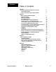
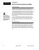
Starting Out Chapter 1 Starting Out With The QPAC Power Control The Q32 SCR Power Control. General Description The QPAC Power Controls are a family of solid-state controls used for electric heating applications. A solid-state power control provides output power that is proportional to the input command signal from a temperature control.
Control Cards Starting Out • • • • • • Solid-state contactor, ac input, CA Solid-state contactor, dc input, CD Burst firing (zero cross) fixed time base, BF Burst firing (zero cross) variable time base, BV Phase angle control, AF * Phase angle control with current limiting, AL * * Note: For 1Ø and 3Ø, 3-leg controls only; not for 3Ø, 3-leg controls. Plug-in transformers (50/60 Hz.) QPAC Modularity Overview.
Mounting Chapter 2 How to Install and Wire the QPAC System Planning This chapter tells you how to install the QPAC. All mounting and wiring information is right here. Watlow power controls are thoroughly tested before leaving the factory, so the QPAC is ready to install when you receive it. WARNING: To avoid potential electric shock and other hazards, all mounting and wiring for the QPAC must conform to the National Electric Code (NEC) and other locally applicable codes.
5.7mm (0.225 in) Mounting 13.5mm (0.53 in) 25.4mm (1.00 in) 7.9mm (5/16 in - 18) 9.7mm (0.38 in) Ensure nut and washer are used below and above fuse 3.8mm (0.15 in) Template for Fuse Holders with QPAC 150A, 575V. Top View Right Side View 88.9mm (3.50 in) minimum 106.4mm (4.19 in) maximum 40.4mm (1.59 in) 19.1mm (0.75 in) 21.1mm (0.83 in) 31.8mm (1.25 in) Top View for Fuse Holders Right Side View Template 9.5mm sent with QPAC 150 Amp 575 V (0.375 in - 16) 50.8mm (2.00 in) 12.7mm (0.
Case Style C Mounting QPAC Case Style C. Model QPAC Case Style C Overall Dimensions. ç Amps Height Width Depth Fans Fuses QPAC-01 150 330mm (13 in) 175mm (6.9 in) 260mm (10.25 in) 1 on heat sink QPAC-01 200 330mm (13 in) 175mm (6.9 in) 260mm (10.25 in) 1 on heat sink QPAC-01 300 330mm (13 in) 175mm (6.9 in) 260mm (10.25 in) 1 on heat sink QPAC-32 150 330mm (13 in) 348mm (14.0 in) 260mm (10.25 in) 2 on heat sink QPAC-32 200 330mm (13 in) 348mm (14.0 in) 260mm (10.
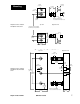
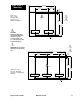
Case Style C Mounting 356mm (14.00 in) 89mm (3.50 in) 178mm (7.00 in) QPAC Case Style C, Q32, 150, 200, 300A, 3-Phase, 2-Leg Mounting Footprint. 16mm (0.63 in) ∫ ç U P MOUNT 298mm (11.75 in) 33mm (13.00 in) ç FAN FAN CAUTION: Mount the QPAC vertically (height dimension vertical) for proper cooling. Failure to do so could result in power control malfunction. 10mm (0.375 in) 4 PL ∫ WARNING: Shock Hazard Heatsinks are electrically Live. ∫ ç 533mm (21.00 in) 92mm (3.63 in) 178mm (7.
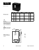
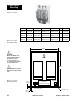
Case Style E Mounting QPAC Case Style E. Model QPAC Case Style E Overall Dimensions. Amps Height Width Depth Fans Fuses QPAC-01 400 to 600 685mm (27 in) 430mm (17 in) 300mm (11.7 in) 1 1 on-board QPAC-01 800 to 1,000 685mm (27 in) 430mm (17 in) 340mm (13.3 in) 1 1 on-board QPAC-32 400 to 600 685mm (27 in) 535mm (21 in) 300mm (11.7 in) 2 2 on-board QPAC-32 800 to 1,000 840mm (33 in) 535mm (21 in) 340mm (13.
Wiring QPAC Wiring Data. Load SemiconducCurrent tor Fuse Rat(amps) ing (amps.) 150 200 200 250 Minimum Bending Radius Recommended Wire Size 3/0 Wire Sized that Lugs Accept Fuse Mounting Lug Torque Internal Allen Wrench 102mm (4 in) 4 to 3/0 *onboard 240 in/lb 3/16 in 250 MCM 114 mm (4.
Output Wiring ∫ L1 *2 Contactors Circuit Breakers or Disconnects *1 L2 WARNING: Shock Hazard Heatsinks are electrically Live. G Heater Load 1A Fuse L1 Fan 120VÅ (ac)/20W T1 L2 L1 L2 *3 On-board, factory installed semiconductor fuses ç CAUTION: Check terminals for tightness before applying power and then recheck terminals after one day of operation. Loose connections can damage the SCR. *4 If Required QPAC-01 Output Wiring for 150 to 1,000A Units.
Output Wiring QPAC-33 Power and Load Wiring for all Units. ∫ WARNING: Shock Hazard Heatsinks are electrically Live. L1 Circuit Breakers L2 or Disconnects *1 Heater Load Contactors If Required L3 Fan 120VÅ (ac)/20W G 3 factory- L1 supplied semiconductor fuses ç CAUTION: Check terminals for tightness before applying power and then recheck terminals after one day of operation. Loose connections can damage the SCR.
Input Wiring ç CAUTION: Built-in noise reduction circuitry on the CA card requires an external load resistor (1000Ω, 25W, typical) across the input when operating from a triac source, to prevent false triggering. Failure to apply this resistor could result in damage to product and equipment or injury to personnel. CA Card Wiring SS Contactor, 120VÅ (ac) Input. Input Signal Wiring When wiring the input signal do not run any signal wires alongside or in the same conduit with the ac power or load wires.
Input Wiring CD Control Card — Contact Closure Input Contactor For a contact closure input to the CD Control Card, the contact is wired to pins 1 and 2 (+) of the input signal connector. A closed contactor input turns the QPAC on and an open contact turns the QPAC off. The input impedance is 10KΩ minimum. 51mm (2.00 in) CD Control Card, SolidState Contactor, Contact Closure Input. 1 08-5286 2 (+) 3 (-) 38mm (1.
Input Wiring AF, AL, BF and BV dc Input. AF, AL, BF and BV DC Input Connections The temperature control output to the Control Cards is wired to the “+” and “-” input terminals of the control card. These cards will accept a 0 to 12VÎ (dc), or 0 to 25mA input signal. They are factory calibrated for 4 to 20mA. If using a voltage or current range other than this, follow bias and gain adjustment instructions in Chapter 3.
Input Wiring Soft Start (Available on the Phase Angle input cards AF and AL only.) Some heater elements change resistance with temperature. Certain types, such as tungsten, change resistance very fast (tungsten increases resistance over 16 times from cold to hot). By slowly increasing the voltage to the heater, the heater element is warmed to full resistance by the time full voltage is applied, thus reducing excessive surge currents. Soft start time on the QPAC is about 6 seconds from power-up.
Input Wiring CT T1 *1 Wh Red Bk Example of Current Transformer Connection to the AL (current limit) Card. Bk 20mA 5A Bk T3 *1 NOTE: Both load leads must pass through the CTs in the same direction.
Input Wiring Single- and Three-Phase Current Transformer Wiring 120VÅ (ac) Single- and Three-Phase DH Option Open Heater or Shorted SCR Detector. *1 NOTE: Interstage transformers (16-0176) are required for all units 150A and above. N.C. Momentary Reset Switch To Alarm or Contactor Customer Supplied Relay (Philips ECG PIY 1055 or equivalent) Open heater when lit 1 2 ç CAUTION: The shorted SCR detector feature will not work with the manual control input.
QPAC system Wiring Example System Wiring The most common failure mode of an SCR is in the shorted state. If this happens, the temperature control can no longer control the SCR and a run-away condition exists. An independent high limit control must be used that will sense unsafe temperature and disengage the circuit breaker via undervoltage trip or a mechanical contactor as shown below. QPAC System Wiring Example, Overtemperature Cutout.
Operation Chapter 3 How to Operate the QPAC Setup Adjustments After the QPAC is installed and wired it may need a few minor adjustments. The three-phase power controls require proper phase rotation. QPACs that use the BF, BV, AF or AL Control Cards may need minor bias and gain calibrations. QPACs that use the AL Phase Angle Current Limit Control Card will need current limit calibration. Refer to the following paragraphs.
Bias and Gain 1. Connect a volt meter across the load or dummy load of the QPAC. Connect a volt meter across, or milliamp meter in series with, the input signal from the temperature controller. NOTE: AL card should be calibrated with a dummy load on the QPAC 2. Apply power to the system. 3. Set the output signal of the temperature controller to zero or its minimum output. The QPAC input is factory calibrated for full off at 4.2mA.
Bias and Gain BV (Rev. B) Control Card. Fixed Bias Connector Gain Pot J3 BV Fixed Bias Connector & Gain Adjustment 1 cut resistor for volts input 5 J1 TB-1 08-5342 Bias Pot Gain Pot 1 AL (Rev. B) Control Card. CT 2 Current Limit Pot (AL Card only) TB-2 1 NOTE: The AL Current Limit must be disabled (pot fully clockwise - CW) before bias and gain can be adjusted.
Troubleshoot Appendix QPAC Troubleshooting QPAC Troubleshooting Guide. A technician can isolate a system problem by first checking if the load is good and the line voltage and temperature signals are present and correct. If the above is true, then the power control may be the problem. The problem may be with the QPAC's control card, transformer or power base. Use this QPAC Troubleshooting Guide to assist with troubleshooting.
Diagnostics Appendix Specific to QPAC-33 Diagnostics The QPAC-33 has four indicator lights for diagnostics. During normal operation, all four will be lit. • Power on Yellow indicator light is on when power is applied to the control. • Phase Loss Yellow indicator light is on when all three phases of line voltage are present. Indicator light will be off if one phase is low or lost. • Phase Rotation Yellow indicator light is on when correct voltage phase exists, even when load is not wired.
Specifications QPAC Specifications Operation • Modular control base with plug-in card and transformer • Plug-in control cards Solid-state contactor, Å (ac) or Î (dc) input Burst fire control, fixed or variable time base Phase angle fire control Phase angle control with soft start and current limiting • Plug-in transformers (50/60Hz) • 120, 208, 240, 277, 380, 415, 480, 575VÅ(ac) operation Power bases • Single-phase (Q01), 1 pair of SCRs • Three-phase (Q32), 2-leg control, 2 pair SCRs.
Specifications • Input impedance 250Ω (move jumper for 5kΩ voltage input), or manual control input • Soft start approximately 6 seconds upon power-up, 1 second upon set point change • Current and interstage transformers included. • Available on Q01 and Q33 models only.
Model Number Model Number Information To order, complete the code number to the right with the information below: Q QPAC = Modular power controller; phase angle, burst, or solid-state contactor with fuse(s) and holder(s) included.
Accessories Accessories Watlow Part Number Model 08-5362 Description Manual Control Kit 16-0176 5A : 20mA Interstage Transformer 0004-0286-0400 400 : 5A Current Transformer 0004-0286-0500 500 : 5A Current Transformer 0004-0286-0600 600 : 5A Current Transformer 0004-0287-0800 800 : 5A Current Transformer 0004-0288-1000 1000 : 5A Current Transformer 16-0008 150A : 5A Current Transformer 16-0045 200A : 5A Current Transformer 16-0073 300A : 5A Current Transformer Watlow Part Number
Accessories Watlow Part Number RPC-5411-42-60H Models Q01, Q33 Description Input Control Card, Phase-angle, w/AL (4 to 20mA, 60 Hz) 08-5289 all Input Control Card, Zero-cross, w/BF (4 to 20mA) RPC-5342-50HZ all Input Control Card, Zero-cross, w/BV (4 to 20mA, 50 Hz) RPC-5342-60HZ all Input Control Card, Zero-cross, w/BV (4 to 20mA, 60 Hz) 08-5285 all Input Control Card, Zero-cross, w/CA (ac input) 08-5286 all Input Control Card, Zero-cross, w/CD (dc input) 08-5287 Q01 Motherboard Assembl
Warranty Warranty The QPAC is warranted to be free of defects in material and workmanship for 36 months after delivery to the first purchaser for use, providing that the units have not been misapplied. Since Watlow has no control over their use, and sometimes misuse, we cannot guarantee against failure.
Index A ac input contactor 14 AF control card auto/manual input 16 current transformer connections 17 input connections 16 potentiometer input 15 process input 15 AL control card auto/manual input 16 current limit adjustments 23 current transformer connections 17–18 input connections 16 potentiometer input 15 process input 15 auto/manual input 16 B BF control card auto/manual input 16 input connections 16 potentiometer input 15 process input 15 bias and gain adjustments 15, 21 burst firing control cards 5
Watlow QPAC Modular SCR Power Control User's Guide Watlow Controls, 1241 Bundy Blvd., P.O.