QPAC Modular SCR Power Control Service Manual Watlow Controls 1241 Bundy Blvd., P.O. Box 5580, Winona, MN 55987-5580, Phone: 507/454-5300, Fax: 507/452-4507 QPAC-SA10-9403 April, 1994 $10.00 Made in the U.S.A.
Use The Manual How to Use the Manual Chapter 1, Page 4 • General Description • Indication of Malfunction • Specifications Chapter 2, Page 8 • Cleaning Fans, Fins,Filter • Tightening Connections • Periodic Test Runs Chapter 3, Page 9 • Base & Firing Cards • Operation Theory Chapter 4, Page 15 • Test Procedures Chapter 5, Page 17 • Troubleshooting Appendix, Page 31 • Waveforms and Schematics • Bench Testing • SCRs Notes The user's manual contains informational notes to alert you to importan
Contents Table of Contents Chapter 1 QPAC Modular SCR Power Control Page General Description .................................................................... 4 Overview ..................................................................................... 5 Replacement Parts ...................................................................... 5 Indication of Malfunction ............................................................. 5 QPAC Specifications ................................................
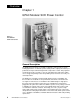
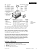
Overview Chapter 1 QPAC Modular SCR Power Control Figure 1 The QPAC-01 SCR Power Control General Description The QPAC Power Controls are a family of solid state controls used for electric heating applications. A solid state power control provides output power that is proportional to the input command signal from a temperature control.
Overview SCRs Unit Rating • 30A • 50A • 75A • 100A • 150A • 200A • 300A Part Numbers QPAC-01 & Q-PAC-32 Q-PAC-33 18-4013 (*1) 18-5179 (*1) 18-4013 (*1) 18-5179 (*1) 18-4013 (*1) 18-5179 (*1) 18-4015 (*1) 18-5179 (*1) 18-5052 (*2) (*NOTE 3) 18-5052 (*2) (*NOTE 3) 18-5052 (*2) (*NOTE 3) Plug-in transformers (50/60 Hz) Part Number • 120VAC 16-0200 • 208/240VAC 16-0201 • 277 16-0202 • 380VAC 16-0208 • 415VAC 16-0207 • 480VAC 16-0203 • 600VAC 16-0209 (consult factory) (*1) SCR Type: Module.
Specifications QPAC Specifications Operation • Modular control base with plug-in card and transformer • Plug-in control cards • Solid state contactor, AC or DC input • Burst firing (zero cross) control, fixed or variable time base • Phase angle control with soft start and current limiting, or digital input • Plug-in transformers (50/60Hz) • 120 VAC operation • 208/240 VAC operation • 380 VAC operation • 415 VAC operation • 480 VAC operation • 600 VAC operation, consult factory • Power bases • Single phase
Output • 120VAC through 480VAC (600VAC, consult factory) • 1, 2, or 3 pole • 30 through 300 amps per pole Power • Frequency 50/60 Hz • Voltage +/- 10%, 120/208/240/277/380/415/480VAC (600VAC, consult factory) Power Dissipation (Watts) • 1.
Procedures Chapter 2 Preventive Maintenance Cleaning Cooling Fans, Fins and Filter Cooling a power control is critical to its reliable operation. Your unit should be inspected and cleaned every six months (more frequently in dirty environments). To achieve this, follow this simple procedure. 1. Remove power from the control. There may be more than one disconnect since the fan power is separate from the main power. 2. Inspect and clean the cooling fans and heat sink fins.
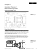
Q01 Chapter 3 Operation Theory of Base and Firing Cards Single Phase Model - Q01 Figure 3 Q01 Board Layout Power Base Operation The Q01 uses one pair of SCRs connected in inverse parallel to control a resistive or inductive load. The main board contains the power supply, output drivers, and connections for the transformer, and the control card. The Q01 accepts all control cards. The standard Q01 power base takes any transformer from 120VAC to 480VAC. 600VAC requires a special base.
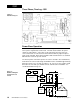
Q32 Three Phase, Two Leg - Q32 Figure 5 Q32 Board Layout Power Base Operation The Q32 uses two pair of SCRs connected in inverse parallel to control two lines of a three phase ungrounded, resistive load. The main board contains the power supply, the output drivers, connections for the transformer and any of the zero cross control cards. It is interlocked so that it will not allow any output if a phase angle card is installed. Q32's will accept 208 to 480 volt transformers as standard.
Q33 Three Phase, Three Leg - Q33 zero cross jumper Power Base Operation Figure 7 Q33 Board Layout and Power Board The Q33 uses three SCR/diode pairs (hybrid) in inverse parallel to control a resistive or inductive ungrounded load. The Q33 has two boards. The main board contains the power supply, phase locked loop (PLL), phase counters, zero cross filter/detector, phase loss, and phase rotation circuitry. The output board contains the SCR protection, artificial neutral, and output drivers.
Q33 Block into 256 parts. When the control card sends out a pulse, U7A picks the correct half cycle, and sends the pulse to U3D which starts counter #1 (U9) and counts to 1 for a short delay. When U1 counts down, it sends a pulse to the output board to fire SCR #1, and resets U3C, and sets U4A. See schematic 02-0798 on Page 35. This starts counter #2 (U10) which counts to 85 (to give a 2.77ms delay). It sends an output pulse to fire SCR #2, resets U4B, sets U4D, and starts counter #3.
Cards AF - Phase Angle Fired (08-5288) The AF card provides a delayed SCR turn ON, providing an infinitely variable voltage and current from full OFF to full ON. The AF card can be used on resistive, inductive, or Tungsten lamp loads. It includes a 10 second soft start, and a missing half cycle detector to put it into emergency shut down (ESD), and retrigger the soft start. A low signal on the ESD terminals puts the QPAC in ESD. The input is factory set for 4 - 20mA into 250Ω.
Cards Figure 12 QBV Board Layout BV - Burst fired with a Variable Time Base (08-5342) The BV card is time proportioning with a variable (very fast) time base. At 50% power, one full cycle is ON, and one full cycle is OFF. At 25% power, it is ON one cycle and OFF for three. At 90%, it is ON nine cycles and OFF for one. As the command signal gets farther from 50% power, the time base gets longer. The maximum cycle time is 1 of 360 cycles. The BV card is standard, setup for 4 - 20mA into 250Ω.
Procedures Chapter 4 Test Procedures Q01 and Q32 No power base adjustments are required on the Q01 and Q32 models. See the bias and gain control card procedures. Q33 Zero Cross Adjustment Follow this step by step procedure to test the Q33 zero cross adjustment. Equipment Needed: • Dual trace oscilloscope 2V/Div Procedure: 1. Set Channel A on the scope to 5 volts per division. 2. Set Channel B to 2 volts per division. 3. Center both channels vertically. 4.
Bias & Gain ❋ NOTE: Any adjustments or troubleshooting of this unit should be done by a qualified technician. These adjustments are necessary for the following control cards: QBF - Bias and Gain adjustments QBV - Gain adjustment QAL - Bias, Gain and Current Limit adjustments QAF - Bias and Gain adjustments Bias and/or Gain Adjustments The bias and gain are factory set for a command signal of 4 - 20mA. However, if minor or major adjustments are required, follow this adjustment procedure. 1.
Procedures Chapter 5 Troubleshooting Indications of Malfunction 1. 2. 3. 4. 5. 6. No output under any circumstances. Full ON output at all times and the load is uncontrollable. Output is not proportional to the command signal (unbalanced output). Operating erratic and inconsistent. Half output. One or more LEDs not lit on the Q33 base Troubleshooting Guidelines Troubleshooting the QPAC should be limited to changing fuses, transformers, SCRs and printed circuit boards.
Q01 Problem: No Heat Blown Fuse This can be done one of two ways. Measure voltage across the fuse. If there is voltage present the fuse is bad. You can also check the fuse for continuity using an ohmmeter. Replace the fuse if necessary. Prior to changing fuses, check the heaters and wiring for a possible short or loose connections. Open Heater Check all the connections from the circuit breaker to the heaters. Measure the heater current. Next, measure the voltage across the heater.
Q01 bad. The resistor will usually be black or dark brown if open. It should read a minimal voltage of < 1V. If it reads line voltage R10 is bad. See Page 5 for ordering a replacement transformer. The QPAC Mother Board is Bad Check the DC voltages at the J1 connector. Place the voltmeter common on pin 7 or 8.
Q01 Problem: Partial Heat This problem can be broken down into two categories: Uncontrollable Heat One of Two SCRs has Shorted (Half Waving is Continuous) This condition exists when one of two SCRs is shorted, allowing half of the AC sinewave to pass through the heater uncontrolled. See Page 19 to test for shorted or open SCRs. The Bias Adjustment is Too High Recalibrate the bias and gain adjustments by following the procedure on Page 16.
Q32 Problem: No Heat Blown Fuse This can be done one of two ways. Measure voltage across the fuse. If there is voltage present the fuse is bad. You can also check the fuse for continuity using an ohmmeter. Replace the fuse if necessary. Open Heater Check all the connections from the circuit breaker to the heaters. Measure the heater current. Next, measure the voltage across the heater. If voltage is present and no current is flowing, there is a bad connection or heater.
Q32 The QPAC Transformer or Resistor Fuse (R10) is Bad Check for AC voltage present at the transformer (T1), see Page 34 for transformer wiring. Be extremely careful! High voltage is present on the transformer connections. If no voltage is present, verify that the resistor fuse is good by measuring across R10. You should be able to visually determine whether or not the fuse is bad. The resistor will usually be black or dark brown if open. It should read a minimal voltage of < 1V.
Q32 The QPAC Mother Board is Bad Refer to the mother board troubleshooting procedure on Page 28. The T1 Load Connection is Open If T1 is open at the heater, the leads will occasionally couple AC back, and turn on L3 and T3 SCRs. Check the load with an ohmmeter at Q32. Problem: Partial Heat Incorrect Phase Rotation The phase rotation must be “A-B-C”. Measure voltage T1 to T2, T2 to T3, and T3 to T1. If it is not within 2 to 5%, reverse any two “L” leads and try again.
Q33 Problem: No Heat Blown Fuse This can be done one of two ways. Measure voltage across the fuse. If there is voltage present the fuse is bad. You can also check the fuse for continuity using an ohmmeter. Replace the fuse if necessary. Open Heater Check all the connections from the circuit breaker to the heaters. Measure the heater current. Next, measure the voltage across the heater. If voltage is present and no current is flowing, there is a bad connection or heater.
Q33 The QPAC Transformer or Resistor Fuse (R10) is Bad Check for AC voltage present at the transformer (T1), see Page 35 for transformer wiring. Be extremely careful! High voltage is present on the transformer connections. If no voltage is present, verify that the resistor fuse is good by measuring across R10. You should be able to visually determine whether or not the fuse is bad. It should read a minimal voltage of < 1V. If it reads open circuit line voltage, R10 is bad.
Q33 Problem: Full or Partial Uncontrollable Heat The SCR Switch is Shorted Remove the control card and power up the QPAC. The output should be OFF. If the unit is still full ON, remove power and disconnect the load wires and measure across L1 and T1 with an ohmmeter. If resistance is low (5Ω or less), the SCR is shorted and must be replaced. See Page 5 for ordering a replacement SCR. A Heater is Partially Shorted Disconnect the control card; the output should be OFF.
Bench Testing Bench Testing Hookups Equipment Required • Dummy Load, min. 1A • 0-15VDC Command (signal) ❋ ❋ NOTE: QPAC-01 Single Phase Load or T2 T1 L2 L1 AC T1 Command Signa 4-20mA or 0-5VDC +- Dummy loads can be made up using 100 watt light bulbs. Bulbs can be put in series to obtain the proper voltage rating. (4each, 100 watt, 120V bulbs per phase for 480V) Control Card An SCR will not latch without a load.
SCRs Testing SCRs in the Unit A shorted SCR will show full uncontrollable line voltage at the T terminals. To test, turn main power OFF, remove the L and T wires. On a QPAC-01, measure resistance from L1 to T1. On a QPAC-32, measure resistance between L1 to T1 and L3 to T3. On a QPAC-33, measure resistance between L1 to T1, L2 to T2, and L3 to T3. A reading of 5 ohms resistance or less indicates that the SCR is shorted. A high resistance reading indicates that the SCR is good.
Cards U12 is used to detect the loss of L2 phase, (phase loss) and U13 is used to detect the proper phase rotation. U7B, U7C, and U7D combined phase loss, phase rotation, PLL, and the thermostat for ESD. Scope picture 2 shows the AC input (L1 to L3) at TP1 and TP6 (FWZ) after zero cross calibration. Scope picture 3 is the high frequency clock TP9 (MCK). Scope picture 4 shows the sequence of operation at approximately 50% power. From top to bottom: 1. FWZ (zero cross reference) 2.
Cards QAF Card (08-5288) Q1 makes up the FWZ signal which is inverted by U3A to give a high signal for all of the half cycle but the zero cross notch. U3B, CR1, R19, and C5 detect missing half cycles which then pulls C7 low with CR2. When C7 is low, the AF card is in ESD. Q4 and Q3 make a linear ramp which is reset at the end of each half cycle by the output of U3A. U1C accepts the input signal and performs the bias and gain function.
Appendix Scope Picture 1 Figure 20 Scope Picture 5 5V/Div 2V/div Figure 16 2ms/div FWZ QPAC-01 and QPAC-32 Base Figure 21 Scope Picture 6 Scope Picture 2 5V/Div 2V/div 2V/Div Figure 17 2ms/div FWZ CA or CD Card (U1-3), QBF Card (TP1) 15ms/div 1) (top) Ramp QBF (TP2) 2) Comparator Out QBF (TP3) Figure 22 Scope Picture 7 Scope Picture 3 2V/div Figure 18 2V/div 2ms/div FWZ (top) Ref Sine Wave for QPAC-33 Base 5us/div MCK (TP 9) QPAC-33 Base , QAD Card (TP 4) Figure 23 200ms/div 2) Gatin
Appendix Scope Picture 10 Figure 28 Scope Picture 13 5V/div 2V/div Figure 25 QBV 1) FWZ (TP1) 5ms/div 2) Output Pulses (TP4) Figure 26 Scope Picture 11 QAF and QAL 2 Second/div 1) ESD (TP4) 2) Soft Start Dump (TP5) 3) Ramp (TP6) Scope Picture 14 2V/div 5V/div Figure 29 Sequence at 50% Output TP1, TP2, TP4, and TP5 QBV Figure 27 Scope Picture 12 5V/div QAD 1) FWZ (TP1) 3) –ZX180 (TP3) Scope Picture 15 5V/div 5V/div 5V/div Figure 30 2ms/div 2) +ZX180 (TP2) QAF and QAL 1) FWZ (TP1) 2)
Watlow QPAC Service Manual Watlow Controls, 1241 Bundy Blvd., P.O.