
User guide

Digital Programmer/Display and
Communications Capabilities
• Programming functions
• Adjust input and output control type, alarms and soft start.
Heater bakeout and current limit prompts also.
• Monitoring functions
• Display input and output values along with actual output current
• Data retention of digital programmer/display upon power failure
via nonvolatile memory
Serial Communications
• RS-232 for single drop control
• EIA-485 for single or multidrop control
• 32 units maximum can be connected. With additional 485
repeater hardware, up to 247 units may be connected
• Isolated
• Modbus™ RTU protocol
• 1200, 2400, 4800, 9600, 19200 baud rates
• Data format 8 data bits, no parity, one stop bit
Controller Power Supply
• Universal line voltage input range 100 to 240VÅ(ac) (+10%, -15%)
@ 55VA maximum
• 50/60Hz ± 5% line frequency independent
• Controller line voltage for electronic power supply can be run on
separate line voltage
Natural Convection and Fan Cooled Models
• Cabinet venting may be required
Power Dissipation (Watts)
• Approximately 1.25 watts/amp per controlled leg
Isolation
• Command signal to load and line/load to ground
2200VÅ(ac) minimum
• On-board semiconductor fuses provide SCR protection
Mounting
• Back panel mount on F35 models
• Other amperage ratings: Removable mounting plate
• Heat sink fins must be mounted in vertical orientation
High Current Terminals
• Touch safe
• 3/8 inch Allen head compression terminals will accept #6 AWG to
350 MCM wire. Allen wrench adapter (included) for 3/8 inch
socket, or 10 mm, 6 point only.
• Torque to 180 in.-lbs. (20.3 Nm.)
• Wire strip to 30 mm (1-1/8 inch)
Controller Terminals
• Touch safe
• 2.5 mm (1/8 inch) blade screwdriver, accepts 12-22 AWG or 2 No.
22-18 AWG wires.
• Torque to 8 in.-lbs. (0.9 Nm.)
• Wire strip to 6 mm (0.24 inch)
• Requires 90C wire insulation rating on line and load terminals.
Operating Environment
• 50°C (122°F) base rating
• 0 to 60°C (32 to 140°F) fan cooled
• 0 to 65°C (32 to 149°F) natural convection cooled
• 0 to 90% RH, non-condensing
• Meets EN50178, Pollution degree 3
Storage Temperature
• -40 to 85°C (-40 to 185°F)
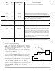
Dimensions
• Width x height x depth
191 mm x 354 mm x 200 mm on N20 through F30 models
(7.5 in x 14.0 in x 7.9 in)
337 mm x 421 mm x 234.1 mm on F35 models
(13.3 in x 16.6 in x 9.2 in)
Shipping Weight
• 10.3 kg. (23 lbs.) on N20 through F30 models
• 17.2 kg. (38 lbs.) on F35 models
Agency Approvals
• UL 508 and C-UL listed, file #E73741
• CE marked, see Declaration of Conformity on page A.14
Specifications (2214)
Power Bases
• Single phase, (2 SCRs)
• 3 phase, 2-leg control, (4 SCRs)
Resistive load only, zero cross firing only
• 3 phase, 3-leg control, (6 SCRs)
• 3 phase, 3-leg control, (6 SCRs) for 4 wire wye loads
• Multizone, two and three single phase zones
Output Control Options
• Zero cross contactor, VÎ(dc) input
• Zero cross control, fixed time base
• Time base 1 or 4 seconds with digital programmer
• Zero cross control, variable time base
• Phase angle control and phase angle control with current limit
(not for 3 phase, 2-leg models)
• Soft start factory default 4 seconds upon power-up, and
adjustable from 0.0 to 120 seconds
• Soft start upon input signal change, output rate of change
adjustable to limit max rate of change from 0.1 to 100% per 0.1
second. Factory default 10%.
• Current transformer included when required
• Line voltage compensated (variable time base and phase angle
controllers only)
• Standby or non-operational mode
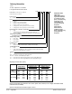
Output Voltage and Current Rating
• 24VÅ(ac) to 120VÅ(ac)(+10%, -15%)
• 200VÅ(ac) to 480VÅ(ac)(+10%, -15%)
• 200VÅ(ac) to 600VÅ(ac)(+10%, -15%)
• 65 through 250 amps per pole, model dependent; see Output
Amperage Chart and Rating Curves
• Minimum load 1 amp rms ac
• Typical leakage current 5mA
• SCCR 200KA with fusing recommendations on page 3.6.
Alarms
• Single alarm relay
• Latching or non-latching
• Alarm silencing (inhibit) on power up for alarm
• Alarm indication LEDs, shorted SCR, open heater, fuse
• Electromechanical relay, form C contact, software configurable
• Minimum load current 10mA @ 5VÎ(dc)
• Rated resistive loads: 3 amps @ 250VÅ(ac) or 30VÎ(dc) max.,
inductive load rating 1.5 amps with a power factor ≥ 0.4 without
contact suppression
Heater Bakeout
• For single phase (phase to neutral) and 3 phase 6 SCR models
only (not for 3 phase, 2-leg models)
• Soft start with over current trip, runs until programmed bakeout
time expires, then goes zero cross or phase angle firing. Factory
default of 24 hours.
• Adjustable 0 - 9999 minutes with over current trip
• Internal current transformer included
Command Signal Input
Analog
• DC contactor 3.5 to 10VÎ(dc), must turn off at 2.5VÎ(dc)
• Field selectable linear voltage and current of low and high points
within 0-20mA and 0-10VÎ(dc)
• Manual control through front panel
• Factory default 0-20mA input
• Voltage input impedance 11kΩ nominal
• Current input impedance 100Ω nominal
Digital
• On-board digital programmer/display and optional serial communications
Retransmit
• Field selectable and scalable within 0-20mA , 800Ω maximum
load or 0-10VÎ(dc), 1KΩ minimum load.
The default is 4-20mA.
• Resolution:
mA ranges = 5μA nominal
VÎ(dc) = ranges 2.5mV nominal
• Calibration accuracy:
mA ranges = ±20μA
VÎ(dc) ranges = ±10mV
• Temperature Stability: 100ppm°C
Appendix Watlow Power Series I A.9