
User guide
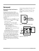
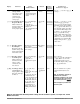

Display Loop
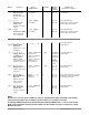
The resting-state display shows one of the following sets of data, depending on controller
setup. The first prompt appears in the top display, the second in the bottom display.
Active: Always.
Appears in Display Loop.
150 r [mA]
151 r [V]
5102 r/w
[dig]
[``)0][``)0] to [2)00] [mA]
(0 to 2000)
[``)0] to [1)00] [V]
(0 to 1000)
[``)0] to [10)0] [%]
(0 to 1000)
0.1 increments
[``In] Analog (mA or V)
or Numeric (%)
Input Signal
Displays mA/V ana-
log input; selects
numeric % power.
Single Zone / Single Phase
Active: Always.
Appears in Display Loop.
198 rn/a
[``47] to [``63]
[47 to 63]
[frEq] Line Frequency
(Hz)
Displays the AC line.
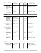
Active: Always.
Appears in display loop.
(In single phase, single zone, only
the center LED operates; in single
phase, 2-zone, or 3-phase, 2-leg,
only the outside LEDs operate; in
3-phase, 3-leg, and multizone,
each zone operates a separate
LED.)
[`___][``-`] or [``_`]
per display
v
[LoAd] Load Activity
Indicator
Displays [``-`] if
load has power
applied.
Active: Any active error.
See Appendix, pp. A.4-7.
195 r n/a
[````] Inactive (0)
[`err] Active (1)
(See Appendix A.7 for
values)
[```] Display Loop
Errors
[alpha) (if any)
Displays present
error conditions.
Active: Any active unmasked
alarm.
Individual Modbus registers may
have [Unla] Unlatched (4)
written to them to clear a
latched alarm.
NOTE: a latched alarm must be
[[``llaatt]]
Latched Inactive (3) before it can be
unlatched.
181 to 190
r/w
[[`alr] Active (1)
[`lat] Latched Active
(2)
[`lat] Latched Inac-
tive (3)
[Unla] Unlatched (4)
[```] Active Alarms
[alpha) (if any)
Displays present
alarm conditions.
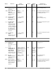
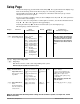
System Information
Display Parameter Range Default Modbus Conditions for
(Modbus Value) Register Parameters to Appear
read/write
Parameters, Chapter 6 Watlow Power Series ■ 6.1
Chapter Six
Parameters
6