
User guide
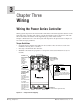

Wiring, Chapter 3 Watlow Power Series ■ 3.3
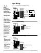
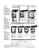
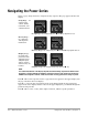
Figure 3.3a – Single Zone Input Wiring
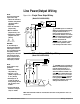
Figure 3.3b – 2-Zone Input Wiring
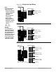
Figure 3.3c – 3-Zone Input Wiring
Power Series
6
5
4
3
2
1
11
10
9
8
7
14
13
12
17
16
15
20
19
18
23
22
21
External Connectors
21 22 23
INPUT 1
18 19 20
INPUT 2
15 16 17
INPUT 3
I
V
+
+
(Current In, 4 to 20mA)
(Common)
(Voltage In, 0 to 10V)
I
V
+
+
(Current In, 4 to 20mA)
(Common)
(Voltage In, 0 to 10V)
I
V
+
+
(Current In, 4 to 20mA)
(Common)
(Voltage In, 0 to 10V)
Power Series
6
5
4
3
2
1
11
10
9
8
7
14
13
12
17
16
15
20
19
18
23
22
21
External Connectors
21 22 23
INPUT 1
18 19 20
INPUT 2
I
V
+
+
(Current In, 4 to 20mA)
(Common)
(Voltage In, 0 to 10V)
I
V
+
+
(Current In, 4to 20mA)
(Common)
(Voltage In, 0 to 10V)
Power Series
6
5
4
3
2
1
11
10
9
8
7
14
13
12
17
16
15
20
19
18
23
22
21
External Connector
21 22 23
I
V
+
+
INPUT 1
(Current In, 4 to 20mA)
(Common)
(Voltage In, 0 to 10V)
NOTE:
Successful installation
requires four steps:
• Choose the controller’s
hardware configuration
and model number
(Appendix);
• Install the controller
(Chapter Two);
• Wire the controller
(Chapter Three); and
• Configure the controller
(Chapters Four, Five
and Six).
ç∫
WARNING:
To avoid damage to
property and equipment,
and/or injury or loss of
life, use National Electric
Code (NEC) standard
wiring practices to install
and operate the Power
Series. Failure to do so
could result in damage,
and/or injury or death.