W A T L O W Optimizing Your Process System with the Series 988 Controller AN APPLICATION GUIDE WATLOW SERIES 988 FAMILY FOR THE
Watlow Mission Statement To Become the Preferred Source of Industrial Heaters, Sensors and Controls by Totally Satisfying Our Customers with Superior Products, Quick Delivery on Specials, as well as Standards, and Intelligent Sales Support. Copyright Watlow Winona, Inc., © 1994, with all rights reserved.
Introduction Welcome to the Watlow Series 988 application guide: Optimizing Your Process System with the WATLOW Series 988. This application guide describes all the features of the Series 988 and how they can be applied to your system. In addition, this guide will walk you through the process of determining the optimal Series 988 for your application. Once you have purchased the controller, the Series 988 Users Manual will guide you through installation and setup of the controller.
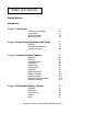
Table of Contents Table of Contents Watlow Mission Introduction Chapter 1 Test Drives 1.
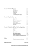
Table of Contents Chapter 5 Standard Features 5.1 Alarms Auto/Manual Diagnostics Input errors Lockout Transmitter power supply 5.2 5.4 5.5 5.6 5.7 5.8 Chapter 6 Specifications 6.1 Input Table Output Table Dimensions Displays and Keys Chart Setup Requirements User's Manual Product Specifications Warranty 6.2 6.3 6.4 6.5 6.6 6.7 6.8 6.
Test Drives Chapter One Test Drives Controlling an Extruder Drying Grain Melting Aluminum Mixing Urethane 1.2 1.4 1.6 1.8 How to use this chapter: This chapter describes four actual applications in which processes are optimized by using Watlow Series 988 controllers. Optimizing Your Process System with the WATLOW Series 988 1.
Basic Control Strategies and Terms Chapter Two Basic Control Strategies and Terms Control Strategies Questions and Answers Glossary 2.2 2.5 2.8 How to use this chapter: This chapter explains control terms and strategies, especially as they apply to the Watlow Series 988 family of controllers. It will help you identify issues specific to your application, and allow you to implement the Series 988 controller in the most cost effective manner, giving you optimal control of your specific system.
Basic Control Strategies and Terms Control Strategies Control Modes A variety of control modes offer various degrees of controllability. The most common modes are on-off and PID control. The PID control category includes varying degrees of complexity that provide accurate, stable control under a variety of conditions. Temperature ON/OFF Control The operation of the ON/OFF control, as the name implies, turns the output device full ON or full OFF.
Temperature a droop condition before it exists. An integration function takes place that automatically compensates for the difference between set point and the actual process. This integration automatically drives the process toward set point. Integration action is prevented until the process enters the proportional band.
Basic Control Strategies and Terms down to a state of equilibrium before making another change. • Remember that the time you need to spend tuning the electronic controller system is relative to the precision of control you need. Proportional Band The proportional band adjustment is the means of selecting the response speed (gain) or sensitivity of a proportioned controller to achieve stability in the system.
Basic Control Strategies and Terms Questions and Answers System Diagram No matter what your application, you must start with an accurate system diagram. A blueprint of the system wiring is typically not a faxable document. When consulting the factory, it’s helpful to be able to fax a system diagram similar to the hand drawings shown in the Test Drives in Chapter One. This diagram should include all inputs, outputs, the controller, the load, any alarms and any connections to other systems or equipment.
Basic Control Strategies and Terms • What is frequent? In order to tightly control a process, the more frequent the better. Unless absolutely necessary, mechanical relays should not be used as the control output. A typical mechanical relay application cycles ON and OFF 86,400 times over a period of one month (30 second cycle time, 24 hours per day). The mechanical relay option is only warranted for 100,000 cycles.
Basic Control Strategies and Terms condensing atmosphere, because the vented case is susceptible to dripping water. If necessary, include an enclosure heater in your system to maintain the proper environment. Is the front panel subject to spray or hosedown conditions? (page 6.8) • The Series 988 has a NEMA 4X-rated front panel. This rating allows the controller to be hosed down directly without damaging the controller.
Basic Control Strategies and Terms Glossary annunciator — a device that uses pilot lamps to indicate the former or existing condition of a system being monitored. derivative — anticipatory action that senses the rate of change of the process, and compensates to minimize overshoot and undershoot. Also see “rate.” ANSI — American National Standards Institute. burst fire — output that switches full AC cycles ON and OFF repeatedly.
Basic Control Strategies and Terms form C — single-pole, double-throw relay that utilizes the normally open (N.O.), normally closed (N.C.) and common contacts. The user has the option of wiring for a form A or form B contact. Refer to the form A and form B above for more information. hunting — oscillation or fluctuation of the process between the set point and process variable. open loop — control system without sensory feedback.
Basic Control Strategies and Terms reference junction — synonymous with cold junction. Also see “cold junction.” retransmit — an analog signal representing a control variable, either the process values or the set point values. RTD — resistance temperature detector. Resistive temperature-sensing device that displays a positive temperature coefficient. supply power to external signal conditioners, transducers or transmitters.
General Software Features Chapter Three General Software Features Auto-tune Burst fire Communications Dead band Digital event Heater current Input filter Input linearization Ramp to set point Remote set point Retransmit (master/remote) Slidewire feedback 3.2 3.3 3.4 3.5 3.6 3.7 3.8 3.9 3.10 3.11 3.12 3.13 How to use this chapter: This chapter describes the software features that are available in Watlow Series 988 controllers.
General Software Features Auto-tune Overview: The auto-tune feature allows the controller to manipulate the process and calculate PID values based on the process response. This relieves the operator from the tedious task of manually tuning the PID parameters to match the characteristics of the thermal system. The point at which the auto-tune takes place is determined by the auto-tune set point parameter.
General Software Features Burst Fire Overview Variable, time-base burst firing from the 988 provides a command signal to an SSR or SCR firing card that translates into a burst of AC cycles. The output is zero-cross fired and always allows at least one AC cycle to pass within the variable time base. The fact that we are zero-cross switching the power device means we enjoy the benefits of low radio frequency (RFI) noise. Burst firing is the preferred mode to control resistive loads.
General Software Features Communications Overview The serial communications feature allows the Series 988 family to receive commands from and transmit data to a master device, usually a computer. Any function that can be performed via the front panel, can also be accomplished using the serial communications port, allowing you to operate the controller from a computer and to store process data on a computer.
General Software Features Dead band Overview The dead band prompts, and , located in the PID menus, determine the amount of interaction between heat (reverse acting) and cool (direct acting) control outputs. The dead band directly offsets the target set point of the cool control output. With a positive dead band, both control outputs will never be on at the same time.
General Software Features Digital Event Overview The digital event input options on the Series 988 controller allow the operator to select one of several software functions with the close of a customer-supplied switch or by a change in DC voltage. The list below outlines the functions that can be controlled with the digital event input. Idle set point lets the operator select, with the close of a switch, a second (idle) set point.
General Software Features Heater Current Overview The heater current feature measures and responds to heater current in a system. This is an ideal method for detecting heater loss in multiple heater applications. The current is measured when output 1 is ON. For instance, if a system has five, 10-amp heaters, the heater current input measures 50 amps regardless of the percent output. To view the heater current press the DISPLAY key and advance to the process 2 prompt .
General Software Features Input Filter Overview In certain applications the process being measured can be unstable, which makes it difficult to control and also makes the constantly changing display difficult to read. The Series 988 input filter can solve these problems by smoothing out just the display or the display and the input signal. You can set a time constant, in seconds, for a low-pass filter that will affect the display only, or you can configure the option to filter the input signal itself.
General Software Features Input Linearization Overview: In many flow applications the output signal from a flow transmitter represents a squared value of the actual flow. The square root must be extracted from the signal to make it useful to the operator. Many flow transmitters offer this feature in the transmitter itself, but this can add significantly to the cost. Using the square root extraction option in the Series 988 controller can save the operator money.
General Software Features Ramp To Set Point Overview Ramp to set point enables the 988 to ramp the set point at a user defined rate. This allows the 988 to start up a system or change between set points at a rate that will not stress the product or system components. The ramp rate is defined in degrees per minute. Ramp to set point can be initiated at start up only, or at start up and also on any set point changes. When a ramp is initiated, the starting point for the ramp is the current process value.
General Software Features Remote Set Point Overview The remote set point feature allows the 988 to use a thermocouple, RTD or process signal at input 2, to establish the set point. This feature gives the 988 the ability to have its set point value manipulated by an external source. A common application would use one ramping controller with a set-point retransmit output to ramp multiple 988’s using the remote set point. Or you could use an analog output from a PLC to send set point values to a 988.
General Software Features Retransmit Overview: The retransmit output can be used to transmit an analog signal representing the value of either input process variable or the target set point variable. The retransmit signal is factory configured as either a milliamp or a voltage signal. In choosing the type of retransmit signal the operator must take into account the input impedance of the device to be retransmitted to and the required signal type, either voltage or milliamps.
General Software Features Slidewire Feedback Overview The 988 can control the position of a valve with a slidewire feedback position indicator. The 988 senses the resistance of the slidewire and compares it to the range low and range high settings to determine the valve position. The controller compares this to the percent output and takes action to match the two by opening or closing the valve. Set the hunt parameter to limit valve hunting. The value is set for the percent of output (0.0 to 100.0).
Enhanced Software Features Chapter Four Enhanced Software Features Cascade Differential Dual PID sets Duplex Ratio 4.2 4.4 4.5 4.6 4.7 How to use this chapter: This chapter describes the software features that are available in the 988 family of Watlow controllers equipped with the enhanced software option. Optimizing Your Process System with the WATLOW Series 988 4.
Enhanced Software Features Cascade Overview Cascade control can handle a difficult process with minimal overshoot, while reaching the set point quickly. This minimizes damage to system components and allows for oversizing heaters for optimal heat-up rates. Systems with long lag times between the energy source (heater, steam, etc.) and the measured process value cannot be controlled accurately or efficiently with a single control loop, because a lot of energy can build up before a response is detected.
Enhanced Software Features In a system controlling a heater this would be the maximum and minimum desired sheath temperatures of the heater. Typically the rangelow term is set below the ambient temperature. Otherwise the system could never fully cool down. settings (outer loop) are then determined by to PID A setting the auto-tune prompt . During the tuning process the set point is determined by multiplying the value by the set point (SP) entered via the front panel.
Enhanced Software Features Differential Overview Differential control allows the Series 988 to control one process at a difference to another process. Input 2 acts as a remote set point input. However the displayed set point indicates the desired difference between input 1 and input 2.
Enhanced Software Features Dual PID sets Overview: Standard software units have a single set of PID parameters. Units with enhanced software can use two independent sets of heat/cool PID parameters, PID A and PID B . To enable dual PID, enter the Global menu and set the algorithm prompt to dual PID . This second set of PID parameters enables the controller to switch between two sets of PIDs, to compensate for changes in the system characteristics.
Enhanced Software Features Duplex Overview Certain systems require that a single process output control both heating and cooling outputs. A Series 988 controller configured with enhanced software and a process output can function as two separate outputs. With a 4 to 20mA output the heating output will operate from 12 to 20mA (0 to +100 percent) and the cooling output will operate from 12 to 4mA (0 to -100 percent).
Enhanced Software Features Ratio Overview This feature allows the 988 to control one process as a ratio of another process. This is especially useful in applications that mix two materials, whether steam, paint or food ingredients. Input 2 of the 988 measures the part of the process that is either uncontrolled or controlled by another device.
Standard Features Chapter Five Standard Features Alarms Auto/Manual Diagnostics Input errors Lockout Transmitter power supply 5.2 5.4 5.5 5.6 5.7 5.8 How to use this chapter: This chapter describes features that, with the exception of transmitter power supply, are included in every controller in Watlow's Series 988 family. Optimizing Your Process System with the WATLOW Series 988 5.
Standard Features Alarms Overview Outputs 2, 3 and 4 can be configured as alarms. To configure an alarm the operator makes several decisions. First we’ll show the difference between a form A, B and C relay. COM (common) NC NO (normally open) Form A Relay COM NC (normally closed) COM NO Form C Relay Form B Relay The relays are shown in the “shelf state,” with no power applied. Note that the form C option allows the operator to configure it as either a form A or a form B output.
Standard Features 5-Silencing Alarm silencing overrides the alarm at power up, and it allows the operator to silence an alarm with the system still in an alarm condition. The silencing is active until the process has entered the safe region located between the low and high alarm settings. Any future deviation outside the safe region triggers an alarm. If the alarm occurs at this point, the output can be silenced by pressing the AUTO/MAN key once, but the alarm message is still displayed.
Standard Features Auto/Manual Overview: When it operates automatically the controller uses an input signal (from a thermocouple, RTD, transmitter, etc.) to determine how best to adjust the output power level to match a set point. This constant monitoring of process variables and the corresponding adjustments in the output power level is referred to as closed-loop control. This is the normal mode of operation for most applications.
Standard Features Diagnostics Overview: The Series 988 Diagnostics menu allows you to read the software revision, ship date, hardware configuration and ambient temperature without removing power from the control. To access the Diagnostics menu press the increment (up-arrow) and decrement (downarrow) keys simultaneously for six seconds. The factory prompt appears in the lower in the display and panel lockout prompt upper display. Press the increment key until diagnosis appears in the upper display.
Standard Features Input Errors Overview When the 988 receives input information it cannot interpret or finds a problem with one of its internal functions, it generates an error code to help identify the problem. The controller switches to manual mode and operates at a fixed power output level, depending upon the type of error code and the selections made in the Global menu. If an input related error occurs, four dashes appear in the upper display and the bottom display indicates the output power level.
Standard Features Lockout Overview: An array of hardware and software lockout features gives you tremendous flexibility in configuring various levels of user access. The Factory and Setup menus can be locked out by setting a DIP switch behind the panel. Four levels of lockout can be set from the front panel. A simple switch or a keylock switch can be connected to a digital event input to lock or unlock access to the front panel.
Standard Features Transmitter Power Supply Overview In an electrically noisy environment or when you have to use a long sensor lead, you may need to use a transmitter to convert the sensor signal to a 4-20mA signal. Normally you would have to buy and install a separate power supply for the transmitter or for other signal conditioning devices, but you can order a Series 988 with a 30mA power supply as one of its outputs.
Specifications Chapter Six Specifications Input Table Output Table Dimensions Displays and Keys Chart Setup Requirements User's Manual Product Specification Warranty 6.2 6.3 6.4 6.5 6.6 6.7 6.8 6.9 How to use this chapter: This chapter contains charts and lists describing specifications of the Watlow's 988 family of controllers. Optimizing Your Process System with the WATLOW Series 988 6.
Specifications Input Table 988 FAMILY INPUT TYPES Input 1 Input 2 Input 3 0-none 1-basic signal conditioner type: J, K, T, N, C, D, Pt 2 high temperature moderate sensor accuracy and stability low and high range low sensor cost 2-universal signal conditioner process input 0-5VDC, 1-5VDC, 0-10VDC, 0-50mVDC, 0-100mVDC, 0-20mA, 4-20mA non-thermal applications sensor determines accuracy and stability long leads of transducer output low and high range best sensor noise immunity moderate to high sensor cost r
Specifications Output Table 988-FAMILY OUTPUT TYPES Output 1 Output 2 Output 3 Output 4 none A solid-state relay good life/low cost B- 0.5A, w RC suppression K- 0.
Specifications Dimensions 4.03" (102mm) WATL W WATL W PROCESS DSPY MODE 2.18" (55 mm) PROCESS L1 L2 DEV L3 L4 4.03" (102mm) DISPLAY % OUT L1 L2 L3 DEV AUTO % OUT MAN SERIES 989 L4 AUTO MAN MODE SERIES 988 2.18" (55 mm) Adjustable Mounting Bracket Panel Panel Cutout Maximum Panel Thickness 0.38" (9.65mm) 3.62" + 0.03 -0.00 (92mm + 0.8) 1.77 + 0.02 -0.00 (45mm + 0.6) 0.68" (17 mm) 4.06" (103 mm) Note: A minimum of 1.66 inches (42.
Specifications Displays and Keys Chart Lower Display Reads Display Loop information, menu or prompt names, or alarm codes — red or green hardware. Upper Display Reads actual process value or operating paramenter value or error code — red or green. DEV (Deviation) LED Indicates that the lower display now reads a deviation-from-the-setpoint value. WATL W % OUT (percent output) LED Indicates that the lower display now reads the percent-output value.
Specifications Setup Requirements Controllers from the Series 988 family require six steps to set up — from system design to system operation. 1 — Build the Part Number This booklet helps with the first step, selecting the features your application will need. The features are recorded in a part number, which Watlow uses to custom build each controller. 2 — Set the DIP Switches The Series 988/989 User’s Manual explains how to set the DIP switches inside the controller chassis.
Specifications User's Manual The Series 988/989 User’s Manual provides the information you will need to install, wire, configure and operate the Series 988 controller, in most applications. Detailed drawings illustrate DIP switch settings, panel mounting and proper wiring of the 988. Easy to use charts and instructions explain how to use the menus and prompts to configure the 988 to your application. A communications manual and a calibration manual are also available for the Series 988.
Specifications Product Specifications Control Mode •Dual input, quad output, optional retransmit of set point or process variable. •Programmable direct and reverse acting control outputs. •One step auto-tuning. Operator Interface •Local/Remote set point capability. •Dual, 4-digit LED displays. Upper: 0.4” (10mm), Lower: 0.3” (8mm). •Mode, Auto/Man, Display, Up and Down keys. Input •Contact input for software function select.
Specifications Warranty The Watlow Series 988 family of controllers is warranted to be free of defects in material and workmanship for 36 months after delivery to the first purchaser for use, providing that the units have not been misapplied. Since Watlow has no control over their use, and sometimes misuse, we cannot guarantee against failure.
How to Choose the Right 988 to Fit Your Application Chapter Seven How to Choose the Right 988 to Fit Your Application Overview Input Output Software Standard Features Hardware Review and Optimize Faxable System Description Model Number Information How to use this chapter: The Watlow 988 family of controllers can be used in an almost infinite variety of applications, in part because the inputs, outputs and many other attributes can be factory configured to match the requirements of many different processes
How to Choose the Right 988 to Fit Your Application Step 1: Overview A. Describe the process that the 988 will control. HELPFUL REFERENCES B. What raw materials go into the process? C. What product does the process create? Chapter 1, Test Drives, provides diagrams and explanations of several different types of applications. Chapter 2, Basic Control Strategies and Terms, explains the basic concepts and vocabulary of control applications. D. List the sensors, switches and controls used in the process. E.
How to Choose the Right 988 to Fit Your Application Step 2: Input A. List all the input devices in your process sketch (Refer to your answer to 1D.). HELPFUL REFERENCES Use the complete input table in Chapter 6, Specifications. See the filled in worksheets in Chapter 1, Test Drives. B. List all of the parameters and specifications that apply to each of the above items. C. Input types must match the appropriate input of the 988. Use the input chart on page 6.
How to Choose the Right 988 to Fit Your Application Step 3: Output A. List all the output devices in your process sketch (Refer to your answer to 1F.). HELPFUL REFERENCES Use the complete output table in Chapter 6, Specifications. Alarms and, transmitter power supply are explained in Chapter 5, Other Features. See the filled in worksheets in Chapter 1, Test Drives. 1 Outputs 2 3 4 A-none solid-state relay B-0.5A w RC suppression K-0.
How to Choose the Right 988 to Fit Your Application Step 4: Software A. Determine what software features your process will require. HELPFUL REFERENCES General Software Features auto-tune 3.2 burst fire 3.3 communications 3.4 dead band 3.5 digital event 3.6 heater current 3.7 input filter 3.8 input linearization 3.9 ramp to set point 3.10 remote set point 3.11 retransmit 3.12 slidewire feedback 3.13 Enhanced Software Features cascade 4.2 differential 4.4 dual PID sets 4.5 duplex 4.6 ratio 4.
How to Choose the Right 988 to Fit Your Application Step 5: Standard Features HELPFUL REFERENCES calibration diagnostics factory settings errors (input) lockout moisture resistance displays and keys setup isolation training manual spec chart warranty 7.6 5.3 5.4 5.5 5.6 5.7 5.8 6.5 6.6 6.7 6.8 6.9 6.10 6.11 A. This section lists features that may be important to your application that are built into all of the 988 family of controllers.
How to Choose the Right 988 to Fit Your Application Step 6: Hardware HELPFUL REFERENCES lockout dimensions display & key chart specifications 5.7 6.4 6.5 6.8 A. Would the controller fit your applications panel better in its vertical configuration (986 or 988) or horizontal configuration (987 or 989)? Be sure to check all dimensions for fit. B.
How to Choose the Right 988 to Fit Your Application Step 7: Review and Optimize HELPFUL REFERENCES Chapter 1, Test Drives, provides diagrams and explanations of several different types of applications. Chapter 2, Basic Control Strategies and Terms, explains the basic concepts and vocabulary of control applications. A. Review the last six steps looking for errors and opportunities to optimize your application’s use of the Series 988 controller.. B.
How to Choose the Right 988 to Fit Your Application Notes Page Optimizing Your Process System with the WATLOW Series 988 7.
Faxable 988the System Description How to Series Choose Right 988 to Fit Your Application date: # of pages: to: from: comp/dept: comp/dept: phone: phone: fax: fax: Output #1 WATLOW 988 Input #1 Key Features: 98_ _ - _ _ _-____ Output #2 98_ _ - ___-____ Software: Input #2 98 _ -____-____ 98_ _ - _ _ _ -____ Power & Hardware: Output #3 98_ _ - _ __-____ Input #3 98 _-____-____ Display colors: 98_ _ - _ _ _ _ - ___ Output #4 digital event standard 98 _ _ - _ _ _ _ - _ _ 98__
How to Choose the Right 988 to Fit Your Application Series 988/989 Model Number Information 98 _ _ - _ _ _ _ - _ _ _ _ Sensor Ranges 100Ω platinum Hardware 6 = Vertical mounting, 24-28 V 7 = Horizontal mounting, 24-28 V 8 = Vertical mounting, 100-240 V 9 = Horizontal mounting, 100-240 V Software A = Standard B = Enhanced (with cascade, ratio, dual PID, differential) #1 Input 1 = Basic thermocouple signal conditioner (excluding Type R, S and B) 2 = Universal signal conditioner #2 Input 0 = None 1 = Basic
Index Index A C A/D overflow error 5.6 A/D underflow error 5.6 accuracy 6.8 actuator interfaces 2.6 address prompt 3.4 agency approvals 6.8 alarm 2 high 5.2 alarm 2 low 5.2 alarm high 3.10 alarm low 3.10 alarm reset 3.6 alarm silencing 1.5, 1.7 alarms 2.6, 5.2, 6.6 algorithm prompt 4.5 aluminum melting furnace 1.6 ambient counts 5.5 ambient temperature 2.6, 5.5 analog output 3.12 annunciation output 2.6 annunciator 2.8 auto mode 5.6 auto reset 2.4 auto-tune 1.3, 2.3, 3.2, 4.3, 4.5, 6.
Index fixed power output 5.6 flow transmitter 1.8, 3.9 form A relay 2.8, 5.2, 6.3 form A/B relay 5.5 form B relay 2.8, 5.2, 6.3 form C relay 2.9, 5.2, 5.5, 6.3 four dashes 5.6 front panel 2.7 front panel lockout 3.6 full lockout 5.7 J JIS 2.9 Joint Industrial Standards 2.9 K G gas valve 5.6 gas-fired furnace 3.13 gaskets 2.7 Global menu 3.6, 3.10, 4.4, 4.5, 4.7, 5.6, 5.7 ground counts 5.5 ground loops 2.5 H hardware 7.8 heat-treat oven 3.12 heater current 1.2, 2.7, 3.3, 3.7 heater current transformer 6.
Index process 2 5.2 process 2 prompt 3.7 process alarms 2.6, 3.7, 5.2 process input 6.2 process retransmit 6.3 process variable 2.9 product specifications 6.8 proportional band 2.4, 2.9, 3.2 proportional control mode 5.5 proportional derivative control with manual reset 2.9 proportional-integral control 2.3 proportional-integral-derivative (PID) 2.3 proportioning control 2.2, 2.9, 2.10 proportioning control with derivative 2.9 protocol 3.4 Q QCD 3.3 QPAC 3.3 questions and answers 2.
Index Prompst, parameters and menus voltage retransmit 5.5 W warranty 6.9 waste water process 3.9 wire length 2.5 wiring 6.6, 6.7 RS-232 5.5 EIA-485/422 5.5 A alarm 2 high 3.10, 5.2 alarm 2 low 3.10, 5.2 retransmit calibrate offset 3.12 ambient counts 5.5 control action output 3.6 address 3.4 alarm 2 energized 5.2 alarm 2 de-energized 5.2 algorithm 4.5 alarm reset 3.6 ambient temperature 5.5 analog output 3.12 retransmit high limit 3.12 retransmit low limit 3.12 auto-tune set point 3.2, 4.3 auto-tune 3.
Index display test 5.5 learn low resistance 3.13 E serial number lower 5.5 error output 5.6 software 5.5 power supply 5.5 solid state 0.5A surppress 5.5 solid state 0.5A 5.5 solid state 2A 5.5 set point 3.10, 4.5 start 3.10 N error 1-1 5.6 error 1-2 5.6 error 1-3 5.6 error 1-4 5.6 error 2-1 5.6 error 2-2 5.6 error 2-3 5.6 error 2-4 5.6 event input 1 3.6, 4.5, 5.7 event input 2 4.5, 5.5, 5.7 error 5 5.6 error 9 5.6 no module 5.5, 5.7 O open loop 5.5 output 3.12 output 1 type 5.5 output 4 type 5.
Designer and Manufacturer of Watlow St. Louis • 12 001 Lackland Road • St.