MINICHEF 2000 TM Applications 24 & 25 Timer Applications Guide Programming & Operating Steps 97 TOTAL CUSTOMER SATISFACTION Watlow Controls 1241 Bundy Blvd. P.O. Box 5580 Winona, Minnesota U.S.A. 55987-5580 (507) 454-5300, Fax (507) 452-4507 WMC2-XAGN-0005-Rev A May 1997 ISO 9001 Registered Company Winona, Minnesota USA $5.00 Made in the U.S.A.
Table of Contents Application 24 Automatic Timer . . . . . . . . . . . . . . . . . . . . . . . 1 Application 25 Manual Timer. . . . . . . . . . . . . . . . . . . . . . . . . 7 Ordering Information . . . . . . . . . . . . . . . . . . . 14 © The Watlow MINICHEF 2000™ Timer Applications Guide is copyrighted by Watlow Winona, Inc., May 1997, with all rights reserved.
24 Application 24 Automatic Timer Introduction to Application 24 . . . . . . . . . . . . . . 1 Configuration Mode Quick Reference . . . . . . . . . 3 Program Mode Quick Reference . . . . . . . . . . . . 4 Step 7 Design a Faceplate Overlay. . . . . . . . . . . 5 Step 8 Operate the Controller . . . . . . . . . . . . . . 6 Application 24 allows you to program six concurrent timers. Overview of Key Steps 1. Install the MINICHEF 2000. 2. Wire the controller. 3. Configure the controller. 4. Program the menus.
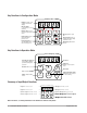
Key Functions in Configuration Mode MINICHEF 2000 Display five-digit, sevensegment numeric LED display. Indicator lights (1 for each key, 2 for heat channels). G H A Edit key (A) Access the next level of parameters or values. Enter key (B) Enter the value and return to previous level. Home key (D) Move to Operation Mode with a two-second key press. C B Edit Up key (C) Move up the lists. Enter D Home Escape key (E) Return to original value when editing a parameter value.
Configuration Mode Quick Reference These are the functions, parameters and values included in the Configuration Mode for this application. You must select Application 24 to access them. For directions, see the Hardware & Software Setup Guide. The Appendix of that guide includes an explanation of all parameters and values.
Program Mode Quick Reference These are the functions, parameters and values included in the Program Mode for this application. You must select Application 24 to access them.. For menu programming directions, see the Hardware & Software Setup Guide. The Appendix of that guide includes a detailed explanation of all parameters and values. Function Parameter Value [M`__] Menu Numbers 1 - 6 [TiNe1] Time 1 Run time of menu. Format varies based on configuration.
Step 7 Design a Faceplate Overlay To complete the installation, you must apply a graphic membrane to the front panel of the controller. The following artwork will help you design and create a membrane for this application. For more dimensions and guidelines, see the Hardware & Software Setup Guide. Suggested End-user Overlay: Your Company Logo Time Time Time 1 2 3 Time Time Time 4 5 6 This Prototyping and Training Membrane Overlay will help you with the configuration and programming steps.
Step 8 Operate the Controller Summary of Key Functions in Operation Mode Key Function A Time 1 B Time 2 C Time 3 D Time 4 E Time 5 F Time 6 Startup Apply power to the controller. [`idle] will appear on the display. If the Real-time Clock Display option is installed and [Setup] / [Cloc`] is set to [``yes], the time of day will appear on the display. Run a Timer 1. With [`idle] on the display, press the key for the timer that you want to run.
25 Application 25 Manual Timer Introduction to Application 25 . . . . . . . . . . . . . . 7 Configuration Mode Quick Reference . . . . . . . . . 9 Step 7 Design a Faceplate Overlay . . . . . . . . . . 10 Step 8 Operate the Controller . . . . . . . . . . . . . 11 Manual Timer Application 25 is a timer, controlling no temperature zones, and controlling one timer. Overview of Key Steps 1. Install the MINICHEF 2000. 2. Wire the controller. 3. Configure the controller. 4. Program the menu. 5.
Key Functions in Configuration Mode MINICHEF 2000 Display five-digit, sevensegment numeric LED display. Indicator lights (1 for each key, 2 for heat channels). G H A Edit key (A) Access the next level of parameters or values. Enter key (B) Enter the value and return to previous level. Home key (D) Move to Operation Mode with a two-second key press. C B Edit Up key (C) Move up the lists. Enter D Home Escape key (E) Return to original value when editing a parameter value.
Configuration Mode Quick Reference These are the functions, parameters and values included in the Configuration Mode for this application. You must select Application 25 to access them. For directions, see the Hardware & Software Setup Guide. The Appendix of that guide includes an explanation of all parameters and values.
Step 7 Design a Faceplate Overlay To complete the installation, you must apply a graphic membrane to the front panel of the controller. The following artwork will help you design and create a membrane for this application. For more dimensions and guidelines, see the Hardware & Software Setup Guide. Suggested End-user Overlay: Your Company Logo 2 1 3 Time 4 Up 6 5 Pause Start/Stop Down This Prototyping and Training Membrane Overlay will help you with the configuration and programming steps.
Step 8 Operate the Controller Summary of Key Functions in Operation Mode Key Function A Not Used B Time C Increment D Pause E Start/Stop F Decrement Startup Apply power to the controller. [`idle] will appear on the display. If the Real Time Clock Display option is installed and [Setup] / [Cloc`] is set to [``yes], the time of day will appear on the display. Set the Timer 1. Press the Time key [TiNe1] and then the time value will appear on the display. 2.
3 When the timer has completed [``end] will appear on the display, the Start/Stop key indicator light will flash rapidly, and an alarm will sound until the Start/Stop key is pressed to acknowledge and shut off the timer. 4. To run the timer again repeat steps 1 thru 3. Note: The controller will not respond if Time is set to 0. Pause a Menu While the timer is counting down you can pause it by pressing the Pause key.
Specifications (1032) Control Mode 1 • Single and dual heat channels, PID or on/off. • Microprocessor-based, programmable, reverse-acting control outputs. • User-selectable embedded application software defines operation of display, keys, inputs, outputs, timing action. • One-step auto-tuning, WatHelp diagnostics, WatCurve temperature compensation.
Ordering Information (1033) F 2 HA- _ _ _ 1 - _ _AA MINICHEF™ 2000 Cooking controller with numerous food equipment application software sets, single and dual channel on/off or PID temperature regulation, timer and machine-function control, microprocessorbased, programmable, auto-tuning, WatCurve, WatHelp diagnostics, 24VÅ (ac) power input, agency approved, flush mounted (membrane faceplate supplied by customer).
Ordering Information: Part Numbers & Accessories MINICHEF 2000 Accessories MINICHEF 2000 Documentation 0836-0442-0000 WMC2-XUGN-0000 A001-0298-0000 0238-0679-0000 0830-0479-0000 A001-0249-0001 A001-0249-0002 Sensor Input Mating Connector, (RIACON #31007106), 6-position, quick-connect terminal, screw connection for 28-14 AWG wires, tighten to 7 in/lb Power Supply and I / O Mating Connector Kit.
Watlow Controls Watlow Controls is a division of Watlow Electric Mfg. Co., St. Louis, Missouri, a manufacturer of industrial electric heating products since 1922. Watlow begins with a full set of specifications and completes an industrial product that is manufactured totally inhouse, in the U.S.A. Watlow products include electric heaters, sensors, controls and switching devices.
Watlow MINICHEF™ 2000 Timer Applications Guide Watlow Controls, 1241 Bundy Blvd., P.O. Box 5580, Winona, MN U.S.A.