MINICHEF 2000 TM Applications 7, 8 & 9 Convection Oven Applications Guide Programming & Operating Steps 97 TOTAL CUSTOMER SATISFACTION Watlow Controls 1241 Bundy Blvd. P.O. Box 5580 Winona, Minnesota U.S.A. 55987-5580 (507) 454-5300, Fax (507) 452-4507 WMC2-XAGN-0002-Rev A May 1997 ISO 9001 Registered Company Winona, Minnesota USA $5.00 Made in the U.S.A.
Table of Contents Application 7 Automatic Convection Oven. . . . . . . . . . . . . . . . 1 Application 8 Automatic Convection Oven . . . . . . . . . . . . . . . 11 Application 9 Manual Convection Oven . . . . . . . . . . . . . . . . 21 Ordering Information . . . . . . . . . . . . . . . . . . . 33 © The Watlow MINICHEF™ 2000 Convection Oven Applications Guide is copyrighted by Watlow Winona, Inc., May 1997, with all rights reserved.
7 Application 7 Automatic Convection Oven One Heat Channel, Six Menus Introduction to Application 7 . . . . . . . . . . . . . . . 1 Configuration Mode Quick Reference . . . . . . . . . 3 Program Mode Quick Reference . . . . . . . . . . . . 4 Step 7 Design a Faceplate Overlay. . . . . . . . . . . 5 Step 8 Operate the Controller . . . . . . . . . . . . . .
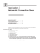
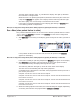
Key Functions in Configuration Mode MINICHEF 2000 Display five-digit, sevensegment numeric LED display. Indicator lights (1 for each key, 2 for heat channels). G H A Edit key (A) Access the next level of parameters or values. Enter key (B) Enter the value and return to previous level. Home key (D) Move to Operation Mode with a two-second key press. C B Edit Up key (C) Move up the lists. Enter D Home Escape key (E) Return to original value when editing a parameter value.
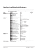
Configuration Mode Quick Reference These are the functions, parameters and values included in the Configuration Mode for this application. You must select Application 7 to access them. For directions, see the Hardware & Software Setup Guide. The Appendix of that guide includes an explanation of all parameters and values.
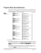
Program Mode Quick Reference These are the functions, parameters and values included in the Program Mode for this application. You must select Application 7 to access them. For menu programming directions, see the Hardware & Software Setup Guide. The Appendix of that guide includes a detailed explanation of all parameters and values. Function [M`__] Menu Numbers 1 - 6 Parameter Value [Stpt1] Set point 1 Temperature of set point 1. [Tine1] Time 1 Run time of set point 1.
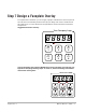
Step 7 Design a Faceplate Overlay To complete the installation, you must apply a graphic membrane to the front panel of the controller. The following artwork will help you design and create a membrane for this application. For more dimensions and guidelines, see the Hardware & Software Setup Guide.
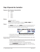
Step 8 Operate the Controller Summary of Key Functions in Operation Mode Key Function A Menu 1 B Menu 2 C Menu 3 D Menu 4 E Menu 5 F Menu 6 Start-up Apply power to the oven. [`idle] will appear on the display. If the Real Time Clock Display option is installed and [setUp] / [time] is programmed, the time of day will appear on the display.
The heat output indicator light - G, just below the display- will light up whenever the controller is calling for heat. When the oven is at operating temperature (above the relative set point minus the ready band) [ready] will appear on the display and the menu key indicator light will flash rapidly. You are now ready to cook with the active menu. • If the oven is at operating temperature, the display goes directly to [ready] without indicating preheat or temperature.
With Sound set to 0, the controller automatically switches to idle in which the controller does not maintain temperature and does not run time. [`idle] or time of day will appear on the display. The menu key indicator light will be off. With Sound set to 1, 2, or 3, [``end] will appear on the display and an audible tone will be emitted. The menu key indicator light will flash rapidly. You can acknowledge the tone by pressing the active menu key or it will time out in 1 to 20 seconds and go into idle.
4. Once the controller goes into idle, the menu key indicator light and the heat outputs will switch off. The controller will not regulate to any temperature. 5. To repeat cooking, repeat steps 1 through 2 or 3. Pause a Menu While cooking, you can pause cooking time by pressing the active menu key once. The menu key indicator light will flash rapidly. [PAUSE] will appear on the display. Countdown time will resume when you press the active menu key again.
Errors The controller will alert you to errors if they occur. Errors are critical problems that shut down the unit. If an error occurs, an error message will appear on the display. You should switch off the power and call for service. See the Appendix in the Hardware & Software Setup Guide for a Troubleshooting Chart and a summary of errors.
8 Application 8 Automatic Convection Oven One Heat Channel, 15 Menus Introduction to Application 8 . . . . . . . . . . . . . . 11 Configuration Mode Quick Reference . . . . . . . . 13 Program Mode Quick Reference. . . . . . . . . . . . 14 Step 7 Design a Faceplate Overlay . . . . . . . . . . 15 Step 8 Operate the Controller . . . . . . . . . . . . . 16 Application 8 allows you to program as many as fifteen menus to control one temperature channel, a fan and cooking time for an automatic convection oven.
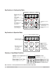
Key Functions in Configuration Mode MINICHEF 2000 Display five-digit, sevensegment numeric LED display. Indicator lights (1 for each key, 2 for heat channels). G H A Edit key (A) Access the next level of parameters or values. Enter key (B) Enter the value and return to previous level. Home key (D) Move to Operation Mode with a two-second key press. C B Edit Up key (C) Move up the lists. Enter D Home Escape key (E) Return to original value when editing a parameter value.
Configuration Mode Quick Reference These are the functions, parameters and values included in the Configuration Mode for this application. You must select Application 8 to access them. For directions, see the Hardware & Software Setup Guide. The Appendix of that guide includes an explanation of all parameters and values.
Program Mode Quick Reference These are the functions, parameters and values included in the Program Mode for this application. You must select Application 8 to access them. For menu programming directions, see the Hardware & Software Setup Guide. The Appendix of that guide includes a detailed explanation of all parameters and values. Function [M`__] Menu Numbers 1-15 Parameter Value [Stpt1] Set point 1 Temperature of set point 1. [Tine1] Time 1 Run time of set point 1.
Step 7 Design a Faceplate Overlay To complete the installation, you must apply a graphic membrane to the front panel of the controller. The following artwork will help you design and create a membrane for this application. For more dimensions and guidelines, see the Hardware & Software Setup Guide. Suggested End-user Overlay: Your Company Logo Heat 1 2 3 Up 4 Menu Select 5 6 Start/ Stop Down This Prototyping and Training Membrane Overlay will help you with the configuration and programming steps.
Step 8 Operate the Controller Summary of Key Functions in Operation Mode Key Function A Not Used B Not Used C Menu Increment D Menu Select E Start/Stop F Menu Decrement Start-up Apply power to the oven. [`idle] will appear on the display. If the Real Time Clock Display option is installed and [setUp] / [time] is programmed, the time of day will appear on the display. Select a Menu 1.
• Activate the menu by pressing the Start/Stop key. • If the oven is not at operating temperature, it will preheat. Meanwhile: The word [pre-`] [`Heat] will appear on the display for a few moments. The Start/Stop key indicator light will flash slowly. The temperature of Channel 1 will be displayed until the operating temperature is reached. The heat output indicator light - G, just below the display- will light up whenever the controller is calling for heat.
With Sound set to 0, the controller automatically switches to idle in which the controller does not maintain temperature and does not run time. [`idle] or current time will appear on the display. The Start/Stop key indicator light will be off. With Sound set to 1, 2, or 3, [``end] will appear on the display and an audible tone will be emitted. The Start/Stop key indicator light will flash rapidly.
With Sound set to 4 or 5, [``end] will appear on the display and the Start/Stop key indicator light will flash rapidly. You must acknowledge the audible signal by pressing the Start/Stop key. Once acknowledged the audible signal is silenced and the controller goes into idle. The Start/Stop key indicator light will be off. 5. Once the controller goes into idle, the Start/Stop key indicator light and the heat outputs will switch off. The controller will not regulate to any temperature. 6.
Temperature Alarms The controller will alert you to temperature alarm conditions if they occur. If an alarm occurs, take action as determined by your supervisor. See the Appendix in the Hardware & Software Setup Guide for a Troubleshooting Chart and a summary of temperature alarms. Errors The controller will alert you to errors if they occur. Errors are critical problems that shut down the unit. If an error occurs, an error message will appear on the display.
9 Application 9 Manual Convection Oven One Heat Channel Introduction to Application 9 . . . . . . . . . . . . . . 21 Configuration Mode Quick Reference . . . . . . . . 23 Step 7 Design a Faceplate Overlay . . . . . . . . . . 25 Step 8 Operate the Controller . . . . . . . . . . . . . 26 Application 9 allows you to program to control one temperature channel, a fan and cooking time for a manual convection oven. Overview of Key Steps 1. Install the MINICHEF 2000. 2. Wire the controller. 3.
Key Functions in Configuration Mode MINICHEF 2000 Display five-digit, sevensegment numeric LED display. Indicator lights (1 for each key, 2 for heat channels). G H A Edit key (A) Access the next level of parameters or values. Enter key (B) Enter the value and return to previous level. Home key (D) Move to Operation Mode with a two-second key press. C B Edit Up key (C) Move up the lists. Enter D Home Escape key (E) Return to original value when editing a parameter value.
Configuration Mode Quick Reference These are the functions, parameters and values included in the Configuration Mode for this application. You must select Application 9 to access them. For directions, see the Hardware & Software Setup Guide. The Appendix of that guide includes an explanation of all parameters and values.
Auto-tuning Note: Before auto-tuning Application 9, [teNp1] in the operations menu must first be set to a value that is typical of your application. (See Hardware & Software Setup Guide for information.) Then set [tHerl] / [tunE1] to [```on]. After you accept [```on], by pressing “Enter,” the controller will display [`tunE] while auto-tuning is taking place. The controller will cancel the auto-tuning process if it cannot be completed in 80 minutes.
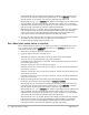
Step 7 Design a Faceplate Overlay To complete the installation, you must apply a graphic membrane to the front panel of the controller. The following artwork will help you design and create a membrane for this application. For more dimensions and guidelines, see the Hardware & Software Setup Guide. Suggested End-user Overlay: Your Company Logo Heat 1 Temp 2 Time 3 Up 4 Fan 5 Start/ Stop 6 Down This Prototyping and Training Membrane Overlay will help you with the configuration and programming steps.
Step 8 Operate the Controller Summary of Key Functions in Operation Mode Key Function A Cook Temp(s) B Cook Time(s) C Up (Increment) D Fan Settings E Start/Stop F Down (Decrement) Start-up Apply power to the oven. [`idle] will appear on the display. If the Real Time Clock option is installed and [setUp] / [time] is programmed, the time of day will appear on the display.
Set the Fan 1. Press the Fan Settings key. [`FAn1] and then the fan setting value will appear on the display. 2. Press the Up or Down key until the value you want appears on the display. 3. Press the Fan Settings key again. The Fan value has been set. [`idle] will appear on the display. The menu you have set becomes the current menu for controller operation.
Set the Fan 1. Press the Fan Settings key. [~FAn1] and then the first fan setting value will appear on the display. 2. Press the Up or Down key until the value you want appears on the display. 3. Press the Fan Settings key again. The first fan value has been set. [~FAn2] and then the second fan setting value will appear on the display. 4. Press the Up or Down key until the value you want appears on the display. 5. Press the Fan Settings key again.
2. With [`idle] or time of day on the display, press the Start/Stop key. If the preheat condition has not been met, the oven will preheat until [ready] appears on the display. Note: You can skip preheat and go directly to the cooking sequence by pressing the Start/Stop key a second time. If the oven is already at operating temperature [ready] will appear on the display. 3. With [ready] on the display, place the food in the oven.
4. When the cooking sequence is finished, [``end] will appear on the display and an audible tone will sound for two seconds. The controller will then go into idle. 5. Once the controller goes into idle, the Start/Stop indicator light will switch off. 6. To repeat cooking, repeat steps 1 through 4. View Actual Oven Temperature While cooking you can view the actual oven temperature by pressing and holding the Cook Temp key for three seconds.
Event Outputs While running a menu when the Configuration Mode [EtYPE] / [FAn``] is set to [````2] : When Low fan speed is on, Event Output 1 is on. When High fan speed is on, Event Output 2 is on. While running a menu when the Configuration Mode [EtYPE] / [FAn``] is set to [````1] :When the fan is on, Event Output 1 is on. ç WARNING: Starting or initiating a menu can cause or initiate fan motion.
Specifications (1032) Control Mode 1 • Single and dual heat channels, PID or on/off. • Microprocessor-based, programmable, reverse-acting control outputs. • User-selectable embedded application software defines operation of display, keys, inputs, outputs, timing action. • One-step auto-tuning, WatHelp diagnostics, WatCurve temperature compensation.
Ordering Information (1033) F 2 HA- _ _ _ 1 - _ _AA MINICHEF 2000™ Cooking controller with numerous food equipment application software sets, single and dual channel on/off or PID temperature regulation, timer and machine-function control, microprocessorbased, programmable, auto-tuning, WatCurve, WatHelp diagnostics, 24VÅ (ac) power input, agency approved, flush mounted (membrane faceplate supplied by customer).
Ordering Information: Part Numbers & Accessories MINICHEF 2000 Accessories MINICHEF 2000 Documentation 0836-0442-0000 WMC2-XUGN-0000 A001-0298-0000 0238-0679-0000 0830-0479-0000 A001-0249-0001 A001-0249-0002 Sensor Input Mating Connector, (RIACON #31007106), 6-position, quick-connect terminal, screw connection for 28-14 AWG wires, tighten to 7 in/lb Power Supply and I / O Mating Connector Kit.
Watlow Controls Watlow Controls is a division of Watlow Electric Mfg. Co., St. Louis, Missouri, a manufacturer of industrial electric heating products since 1922. Watlow begins with a full set of specifications and completes an industrial product that is manufactured totally inhouse, in the U.S.A. Watlow products include electric heaters, sensors, controls and switching devices.
Notes 36 ■ Watlow M I N I C H E F 2000 Application 8
Notes Application 8 Watlow M I N I C H E F 2000 ■ 37
Watlow MINICHEF™ 2000 Convection Oven Applications Guide Watlow Controls, 1241 Bundy Blvd., P.O. Box 5580, Winona, MN U.S.A.