MINICHEF 2000 TM Hardware & Software Setup Guide For All Applications 97 TOTAL CUSTOMER SATISFACTION Watlow Controls 1241 Bundy Blvd. P.O. Box 5580 Winona, Minnesota U.S.A. 55987-5580 (507) 454-5300, Fax (507) 452-4507 WMC2-XSGN-0000-Rev A May 1997 ISO 9001 Registered Company Winona, Minnesota USA $15.00 Made in the U.S.A.
WATLOW MINICHEF™ 2000 All Applications Hardware & Software Setup Guide Introduction . . . . . . . . . . . . . . . . . . . . . . . . .3 Application Selection Table . . . . . . . . . . . . . . .4 Overview of Key Steps . . . . . . . . . . . . . . . . . .5 General Description . . . . . . . . . . . . . . . . . . . .6 Step 1 Installation . . . . . . . . . . . . . . . . . . . . .8 Step 2 Wiring . . . . . . . . . . . . . . . . . . . . . . .12 Step 3 Configure the Controller . . . . . . . . . . .
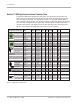
Application Number Guide Cook-&-Hold Ovens Application 1 . . . . . . . . Automatic Cook-&-Hold Oven with Meat Probe Option Application 2 . . . . . . . . Automatic Cook-&-Hold Oven with Meat Probe Option Application 3 . . . . . . . . Automatic Cook-&-Hold Oven Application 4 . . . . . . . . Automatic Cook-&-Hold Oven Application 5 . . . . . . . . Manual Cook-&-Hold Oven with Meat Probe Option Application 6 . . . . . . . . Manual Cook-&-Hold Oven Convection Ovens Application 7 . . . . . . . .
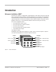
Introduction Welcome to the MINICHEF 2000™ The MINICHEF 2000 is a configurable, time/temperature and machine function controller that is preprogrammed for dozens of cooking applications. Its compact size and optional horizontal/vertical orientation facilitates streamlined equipment design. It withstands rigorous application environment conditions, with an 80ºC ambient rating and superior EMI/RFI immunity. It is also backed by Watlow’s exclusive three-year warranty.
Introduction MINICHEF™ 2000 Application Software Selection Table To select the application software that best suits your equipment and purpose, first locate the type of equipment in the left column, then check the other columns for features and options you need. The application number is on the right (Appl#). Make a note of the application number. You will be using this number later when programming your controller.
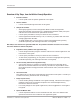
Introduction Overview of Key Steps, from Installation through Operation: 1 Install the controller • 2 Wire the controller • 3 Use the panel knock-out pattern guidelines in this guide. Use the connector/wiring information in this guide. Configure the controller • After applying power, use the Configuration Mode to enter the equipment Application Number (from the MINICHEF 2000 Software Selection table), set up the controller and access the thermal optimization functions.
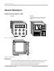
General Description General Description Getting to know your MINICHEF™ 2000 Front view Back view Shown with mating connector terminals installed. Mating connectors and terminals are purchased separately. 2.00 in. IIIIIIIIII IIIIIII IIIIIIIIII IIIIIIII OPER. RANGE 0-80 DEG C 2=OC+ 3=OC35=OC+ 6=OC48=EI1+ 9=ALARM G H A B C D E F 11=EI2+ 12=EI113=L2 24V 14=L1 24V 15=EI2- 3.00 in. NSF c 13 10 7 4 1 14 11 8 5 2 15 12 9 6 3 WATLOW CONTROLS INPUT#1 NOT INPUT#2 NOT TC+ TC- USED TC+ TC- USED 3.
General Descrip tion Mating Connectors (purchased as an accessory — not included): See Accessories ordering information about the following mating connectors: Sensor Input Mating Connector: RIA Electronic Inc. RIACON #31007106, 6-position, quick-connect terminal, screw connection for 28-14 AWG wires, tighten to 7 in/lb. Power Supply and Input/Output Mating Connector Kit: Kit includes: one AMP #1640523-0 quick-connect terminal and fifteen AMP #641300-1 crimp pins.
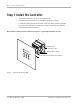
Step 1 Install the Controller Step 1 Install the Controller • Select sheet metal (16-, 18-, 20- or 22- gauge panel). • For panel knock-out patterns, see subsequent pages of this guide. • Use #6-32 mounting studs x 0.50” length minimum, either pressed or welded. • Install the unit with either a horizontal or vertical mounting collar position. • Install mating connectors to unit. Note: This device should be used in systems that incorporate a separate high limit device for safety.
Step 1 Install the Controller in . in . 1. 87 5 1. 40 5 in . 1. 00 0 in . 0. 50 0 in . 0. 00 0 in . 0. 50 0 in . 1. 00 0 in . 1. 40 5 1. 87 5 in . Panel Knock-out Pattern for a Mounting Collar in a Horizontal Position 2.535 in. 2.125 in. .875 in. ref 1.660 in. 1.530 in. 1.250 in. ø0.53 in. (6) 0.875 in. ø0.135 in. (10) 0.375 in. 0.125 in. 0.000 in. #6-32 stud (4) minimum recommended length 0.50 in. 0.250 in. 1. 1. 37 37 5 5 in in . . C/L . 1. 87 5 in 1. 33 8 0 00 1.
Step 1 Install the Controller . 5 in . 40 1. 00 0 in . 1. 0. 50 0 in . 00 0 in . 0. 0. 50 0 in . in 0 00 1. 1. 40 5 in . Panel Knock-out Pattern for a Mounting Collar in a Vertical Position 3.000 in. 2.535 in. .875 in. ref 1.660 in. 1.530 in. 1.250 in. ø0.53 in. (6) 0.875 in. ø0.135 in. (10) 0.375 in. 0.000 in. 0.250 in. 0.750 in. . . in in 1. 37 5 0 00 #6-32 stud (4) minimum recommended length 0.50 in. 1. 0 00 1. 1. 37 5 in in . .
in . in . 33 8 1. 1. 00 0 in . 0. 50 0 in . 0. 00 0 in . 0. 50 0 in . 00 0 1. 1. 33 7 in . Step 1 Install the Controller 3.000 in. 2.462 in. .800 in. ref 1.662 in. 1.530 in. 1.250 in. ø0.53 in. (6) 0.875 in. ø0.135 in. (8) 0.375 in. 0.000 in. 0.750 in. . in 0 00 #6-32 stud (4) minimum recommended length 0.50 in. 1. 1. 00 0 in . C/L Figure 11 — Pattern for vertical panel 20- or 22-gauge thick.
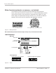
Step 2 Wire the Controller Step 2 Wire the Controller Position the connector with the beveled edges at the top. Not all software applications use or require wiring to all inputs and outputs. For specific information consult the guide for the application you are using. Note: The following illustration is a view of the back of the controller, not of the mating connector. Power Wiring Fuse L1 L2 13 14 13 14 15 10 11 12 7 8 9 4 5 6 1 2 3 Figure 12a — 24VÅ (ac) Low Voltage.
Step 2 Wire the Controller Dual RTD Option (platinum) F2__–2___–____ (100Ω RTD, curve selectable) F2__–3___-____ (500Ω RTD, curve selectable) F2__–4___-____ (1000Ω RTD, curve selectable) Input 1 Wiring S1 Input 2 Wiring S2 1 S1 2 3 S2 4 5 6 Figure 13a — 2-wire RTD. Input 1 Wiring S1 S2 1 2 S3 Input 2 Wiring S1 3 S2 4 S3 5 6 Figure 13b — 3-wire RTD: (will function as a 2-wire RTD).
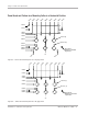
Step 2 Wire the Controller Output 1 Ext. Load Note: The following illustrations are views of the back of the controller, not of the mating connector. 4 1 13 14 15 10 11 12 7 8 9 4 5 6 1 2 3 F2__–_1__–____ Figure 14a — Switched DC Option (5V nominal, 30mA, non-isolated). Fuse L1 Com 4 L2 NO 1 13 14 15 10 11 12 7 8 9 4 5 6 1 2 3 Ext. Load Form A, 0.
Step 2 Wire the Controller Output 2 Ext. Load Note: The following illustrations are views of the back of the controller, not of the mating connector. 10 7 13 14 15 10 11 12 7 8 9 4 5 6 1 2 3 F2__-__1_–____ Figure 15a — Switched DC Option (5V nominal, 30mA, non-isolated). Fuse L1 Com 10 L2 NO 7 13 14 15 10 11 12 7 8 9 4 5 6 1 2 3 Ext. Load Form A, 0.
Step 2 Wire the Controller Event Output 1 and Event Output 2 Note: The following illustrations are views of the back of the controller, not of the mating connector. 14 15 13 14 15 10 11 12 10 11 12 7 8 9 7 8 9 4 5 6 4 5 6 1 2 3 1 2 3 Event Output 1 2 Ext. Load 3 F2__-___1-____ Event Output 2 6 5 Ext. Load 13 (switched dc, 5V nominal, 30mA, non-isolated outputs) Figure 16a — Event Outputs.
Step 3 Configure the Controller Step 3 Configure the Controller Overview of Configuration • Get to know the keys and how they function in different modes. • Review configuration and programming procedures in this guide. • Choose applications, functions, parameters and values (see Application Software Selection Table in this guide). • Review the operating instructions (in each application guide). • Get a complete idea of how the application works.
Step 3 Configure the Controller Software Structure The MINICHEF 2000 software uses three modes — Configuration Mode, Programming Mode and Operation Mode — and each mode contains up to three levels of functions, parameters and values. The Operation Mode is the default mode. MINICHEF 2000 [M``1] G A From the Menu Programming Mode, press the Home and Escape keys for two seconds to view the functions. FUNCTIONS Press the Up- or Down-arrow key to scroll through the functions.
Step 3 Configure the Controller MINICHEF 2000 [`idle] G A From the Operation Mode, press the Up- and Downarrow keys for two seconds to view the menus. H C B Edit Enter D F E Home Escape Press the Enter key to return to idle. MENUS Press the Up- or Down-arrow key to scroll through the menus. [M``1] [M``2] [M``3] B Enter D Home • • • Press the Edit key to view the parameters of the selected menu. Press the Home key for three seconds to return to idle.
Step 3 Configure the Controller Configuration Mode Quick Reference This is a list of all functions, parameters and values that are available through the Configuration Mode. (They are not all available for every application.) For a detailed explanation of parameters see the Appendix in this guide.
Step 3 Configure the Controller Function [tHErl] Thermal Parameter [tyPE`] [HYSt1] [HYSt2] [Pid`U] [tune1] [tune2] [ProP1] [rSEt1] [int`1] [rAtE1] [dEr`1] [CYcL1] [ProP2] [rSEt2] [int`2] [rAtE2] [dEr`2] [CYcL2] Temperature Control Type Hysteresis 1 Hysteresis 2 PID Units Auto-tuning, Channel 1 Auto-tuning, Channel 2 Proportional Band 1 Reset (integral) Gain 1 Integral Gain 1 Rate (derivative) Gain 1 Derivative Gain 1 PID Cycle Time 1 Proportional Band 2 Reset (integral) Gain 2 Integral Gain 2 Rate (deriv
Step 3 Configure the Controller On/off Temperature control On/off control switches the heat outputs either full on or full off, depending on the temperature sensor input, set point and hysteresis values. The hysteresis value creates a buffer zone that increases the time interval that the output is off or on. With hysteresis set to 1º the process value would stay closer to the set point, but the output would switch on and off more frequently.
Step 3 Configure the Controller Configuration Procedure Power up the control (24VÅ (ac) source required). 1. Access the Configuration Mode by pressing the Up-arrow and Down-arrow keys simultaneously for two seconds. [m``1] for automatic applications will appear on the display. [-----] will appear in manual applications. Then press the Home key and the Escape key simultaneously for two seconds. [etype] will appear on the display. It is the first in a list of functions. You are now in the Configuration Mode.
Step 3 Configure the Controller Note: When you are configuring your controller, always edit [Etype] and set the application number first (for example, [appl`] [```20]). The parameters that follow are based on it. In general, parameters that appear earlier on the list can influence the parameters and values that follow. 6. To change a value: press the Down-arrow key or the Up-arrow key. MINICHEF 2000 [```28] G H B Edit C Accept E F Back-Up 7.
Step 4 Program the Menus Step 4 Program the Menus Program Mode Quick Reference These are the functions, parameters and values that may be included in the Program Mode. Not all parameters will appear. Different parameters are relevant in different application numbers. For a detailed explanation, see the Appendix in this guide. Function [M`__] Menu Numbers XX Parameter Value/Description [Stpt1] Set point 1 Temperature of set point 1.
Step 4 Program the Menus [ALArn] Mid Menu Alarm [none], [Stir], [Add], [FLiP], [turn], [ALErt] [AtinE] Alarm Time Time before end of menu 0 - [tiNE1] (in seconds) [Hstpt] Hold Set Point Temperature at which the oven will operate during hold sequence Temp range low to temp range high. [Htine] Hold Time Run time of hold sequence. 0 = infinite. A setting >0 = hold time.
Step 4 Program the Menus Procedure to program the menus This procedure applies only to automatic applications. Menus for manual applications are explained in the application guides. 1. To enter the Program Mode, press the Up-arrow and Down-arrow keys simultaneously for approximately two seconds. [m``1] will appear on the display. This is menu number 1, the first in a list of sev- eral. You are now in the Program Mode.
Step 4 Program the Menus 5. To edit a value: with the parameter on the display, press the Edit key. The first value in a list of values will appear on the display. MINICHEF 2000 MINICHEF 2000 [650`f] stpt1] G G H H A B Edit Accept D E Exit Back-Up A B Edit Accept D E C Exit Back-Up C F F 6. To change a value: press the Down-arrow key to move down, press the Up-arrow key to increment up.
Step 5 Set Controller Security Step 5 Set Controller Security To Set Menu Security Lock Return to the Configuration Mode, to the [Setup] Function, and program the [Loc``] Parameter to adjust end-user access. When [loc``] is set to [``yes] the end user does not have access to the Menu Programming Mode and can only view parameter values. When [loc``] is set to [```no] the end user has access to the Menu Programming Mode and can change parameter values.
Step 6 Set the Real-time Clock Step 6 Set the Real-time Clock These instructions are optional and apply only to controllers that are purchased with the Real-time clock (time of day) option. (Part number example: F2 _ _ - _ _ _ _ - 1 _ _ _) To set the time of day 1. Press the Edit key and Home key simultaneously for approximately 3 seconds. You are now in the Real-time Clock Program Mode.
Step 7 Design Membrane Overlay Step 7 Design Membrane Overlay In Step 7, design the membrane overlay for the front controller panel. Follow the design guidelines here, but for suggestions about designs suitable for specific applications, see the Suggested Overlay Design in each application guide. 1. Design guidelines 1.250 in. R .060 in. in. Ref. 1.250 in. 4.125 Red transparent window (no adhesive in this area) 2.413 in. 2.125 in. 2.062 in. .700 in. Ref. 1.713 in. 1.530 in. 1.250 in.
Step 7 Design Membrane Overlay 1.250 in. 1.250 in. 3.250 in. Ref. Red transparent window (no adhesive in this area) 3.000 in. R .060 in. 2.413 in. 2.125 in. 2.062 in. .700 in. Ref. 1.713 in. 1.530 in. 1.250 in. .875 in. Mounting collar outline (shown in horizontal orientation) .375 in. .125 4.125 in. Ref. Watlow keys (6) (no adhesive in these areas) 1.000 in. .000 in. .500 in. Mounting studs (ref) (4) .500 in. .750 in. 1.000 in. .000 in. in.
Appendix Appendix Troubleshooting Chart . . . . . . . . . . . . . . . . .34 Definitions of Functions, Parameters, Values .44 Definitions of Alarms and Errors . . . . . . . . . .55 Glossary of Terms . . . . . . . . . . . . . . . . . . . .58 Specifications . . . . . . . . . . . . . . . . . . . . . .60 Ordering Information . . . . . . . . . . . . . . . . . .61 Warranty and Returns Policy . . . . . . . . . . . . .63 Index . . . . . . . . . . . . . . . . . . . . . . . . . . . .64 Declaration of Conformity . .
Tr oubleshooting Chart MINICHEF™ 2000 Troubleshooting Chart Symptom/Indication Possible Causes Possible Solutions Main display is blank. No indicator lights. • • • • • • • Check the controller mating connectors and system harness assemblies for proper installation. • Cycle the power to the controller: off-on. • Check power supply, fuses, switches, breakers, connectors, wiring for proper connection. System power switch is off. System fuse is blown. System circuit breaker is tripped.
Troubleshooting Chart Symptom/Indication Possible Causes Possible Solutions [Err`6] appears on the display •A/D Overflow Error has occurred on channel 1. • Temperature sensor or circuit for channel 1 is open or damaged. • Temperature sensor for channel 1 is incompatible with controller. • Channel 1 measures a condition above the controller temperature range. • Evaluate condition of channel 1 sensor and circuitry. • Confirm temperature sensor compatibility.
Tr oubleshooting Chart Symptom/Indication Possible Causes Possible Solutions [Err`9] appears on the display • A/D Underflow Error has occurred on channel 2. • Temperature sensor for channel 2 is incompatible with controller. • Temperature sensor lead wires for channel 2 are improperly terminated (lead wires are reversed). • Channel 2 measures a condition below the controller temperature range. • Confirm temperature sensor compatibility.
Tr oubleshooting Chart Symptom/Indication Possible Causes Possible Solutions [Err`12] appears on the display • Over-range Error has occurred on channel 2. • Controller measures a temperature above the allowable operating range. • Temperature sensor lead wires for channel 2 are improperly terminated (lead wires are reversed). • Controller is misapplied. • Refer to sensor wiring instructions. • Refer to controller specifications. • System may need to cool down.
Tr oubleshooting Chart Symptom/Indication Possible Causes Possible Solutions [PrOC1] appears on the display. System seems to be overheating. Absolute Process Alarm for channel 1 has occurred. • Channel 1 temperature sensor measures a value that exceeds the maximum allowable temperature defined by the program. • System equipment failure. • Determine if Absolute Process Alarm is required for channel 1.
Troubleshooting Chart Symptom/Indication Possible Causes [`Hi`1] appears on the display. System seems to be overheating. Deviation Alarm indicating a high temperature condition for channel 1. • Channel 1 sensor measures a high temperature that exceeds the allowable deviation above the programmed setpoint. • Determine if High or Low Deviation Alarms are required for channel 1.
Tr oubleshooting Chart Symptom/Indication Possible Causes Possible Solutions [`LO`2] appears on the display. System seems to be underheating. Deviation Alarm indicating a low temperature condition for channel 2. • Channel 2 sensor measures a low temperature that exceeds the allowable deviation below the programmed setpoint. • Determine if High or Low Deviation Alarms are required for channel 2.
Troubleshooting Chart Symptom/Indication Possible Causes Possible Solutions Keys inoperative or hard to press. • Misalignment of controller to metal faceplate. • Menu key is inactive due to programmed menu time set to zero. • Operator error. • Defective key switch. • Ensure proper mounting of controller. • If Menu key is inoperative, verify that a time greater than zero is programmed into the Menu program for that key. • Refer to the programming guide. Consult factory. • Return to factory.
Troubleshooting Chart Symptom/Indication Possible Causes Possible Solutions Time of day is inaccurate • Real-time Clock is not programmed properly. • Battery is low. • Refer to programming guide to reset the time of day. • If problem persists, return to factory. Programmed Menus are being changed or tampered with. Menu Program Security has not been set. To secure the Menu programs, set the [Loc``] parameter to [``YES]. Software Application Numbers are being changed or tampered with.
Tr oubleshooting Chart Symptom/Indication Possible Causes Possible Solutions Cannot change the value of a parameter while in the Configuration Mode. Operator error. • View the parameter name on the display. Display should be flashing. Press the EDIT key first, before using the UP and DOWN keys. • If attempting to set the software application number ([APPL`]), the Application Number Security Lock may be set; set the [A_Loc] parameter to {```no].
Definitions of Functions, Parameters and Values Definitions of Functions, Parameters and Values Configuration Mode [etype] Equipment Type Function Configures control for application and sounds. [APPl`] Application Number Selects the application software set for the controller. Range: 1-20 Default: 20 [a_Loc] Application Number Security Lock Choose between [``yes] and [```no] to lock the Application Number. When [a_Loc] is set to [``yes], the Application Number is not adjustable.
Definitions of Functions, Parameters and Values [idLE2] Idle Temperature Number 2 This is the effective setpoint when you press the idle two key. This idle setpoint can only be regulated to during the idle state. Range: temp range low - range high Default: temperature range low [Melt] Oil Melt Cycle Turns the melt feature on or off. This feature will allow the heaters to come on at only 10% power when the temperature is below 212°F. This is visible on all deepfat fryer applications.
Definitions of Functions, Parameters and Values Setup Function, continued [time] Time Display Format Selects the time display format in minutes/seconds, hours/minutes, or hours/ minutes/ seconds and will only appear when the selected application software set uses time for any of its operations. Range: [NNNSS] [`HHNN] [HNNSS] Default: [HNNSS] [Chirp] Key Chirp Turns the key chirp function on or off. The key chirp function makes a short audible sound whenever a valid keypress has been made.
Definitions of Functions, Parameters and Values [tr`lo] Temperature Range Low Sets an absolute lowest setable temperature set point. This parameter appears only when the selected application software set uses at least one temperature output. Range: 0ºF (-18ºC) for rtd inputs, 32ºF ( 0ºC) for tc inputs to the value of [tr`Hi] Default: 32ºF [tr`Hi] Temperature Range High Sets an absolute highest setable temperature set point.
Definitions of Functions, Parameters and Values Setup Function, continued [aldl1] Low Deviation Alarm, Channel 1 Sets a relative low deviation temperature alarm. A low deviation alarm occurs when the input 1 temperature (including offset) is below set point minus this setting. This parameter only appears when the selected application software set uses temperature input 1 and [al``1] is set to either [``deu] or [`both].
Definitions of Functions, Parameters and Values [HySt1] Channel 1 Hysteresis Sets the relative switching hysteresis size for output 1. This parameter only appears when the selected application software set uses a temperature output from channel 1 and [type`] is set to [onOFF]. Range: 1 to 99ºF / 1 to 55ºC Default: 3ºF / 2ºC [HySt2] Channel 2 Hysteresis Sets the relative switching hysteresis size for output 1.
Definitions of Functions, Parameters and Values Thermal Function, continued [der`1] Channel 1 Derivative Sets the derivative gain for ot 1. A value of 0.00 shuts the derivative off. This parameter appears when the selected application software set uses temperature output 1 and [type`] is set to [``Pid] and [Pid`U] is set to [```si]. Range: 0.00 to 9.99 minutes Default: 0.00 minutes [Cycl1] Channel 1 Cycle Time Sets the PID cycle time for output 1.
Definitions of Functions, Parameters and Values [`diag] WatHelp Diagnostics Function Allows the viewing of information that is useful when servicing or troubleshooting the system. [date`] Date-of-Manufacture Code Shows the manufactured date code of the controller. Cannot be changed. [ser`n] Serial Number Shows the serial number of the controller. Cannot be changed. [Part1] Part Number 1 Shows the first four characters of the controller part number. Cannot be changed.
Definitions of Functions, Parameters and Values Diagnostics Function, continued [inPut] Event Input Test To assist in system troubleshooting,shows the on/off state of the event inputs. A number alternatelyappears on the display. If number =0, both inputs are open If number =1, input 1 is closed, input 2 is open If number =2, input 1 is open and input 2 is closed If number =3, both inputs are closed [teNp1] Channel 1 Input Shows the input 1 temperature, with no offset added.
Definitions of Functions, Parameters and Values Program Mode [m``1] Menu Number The number of the menu to program. Range: 1 - x (The total number of menus depends on the application.) Default: 1 [stpt1] Set Point 1 This is the first cook set point temperature. Range: Minimum and maximum temperatures programmed in the Configuration Mode Default: range low [tinE1] Time This is the first cook time.
Definitions of Functions, Parameters and Values Program Mode, continued [StPt3] Set Point 3 This is the third cook set point temperature. Range: range low to range high Default: range low [tinE3] Time 3 This is the third cook time. Range: depends upon time format, other time settings, and end application Default: 0 [Fan`3] Fan 3 This is the third fan setting. Range: On, OFF, Lo, Hi Default: OFF [StPt4] Set Point 4 This is the fourth cook set point temperature.
Definitions of Temperature Alarms Definitions of Temperature Alarms If there is a problem during operation, an alarm message will appear on the main display. Alarm messages are self clearing. They will go away when the condition causing the alarm goes away. Only one alarm will be displayed at a time. The alarm with the highest priority will be the one displayed.
Definitions of Errors Definitions of Errors This control has the ability to detect different error conditions. The outputs of the control will be shut off when any error condition occurs. If a menu is running, it will be canceled upon any error condition. Only one error will be displayed at a time. The error with the highest priority will be the one displayed. When displaying errors, an error message will alternate with the normal display. Errors will only be displayed in the operational mode.
Definitions of Errors Over range error [Err`8] (channel 1), [Err12] (channel 2) The over range error occurs when the control is unable to accurately calculate the temperature even though the A/D is able to measure the signal.
Glossar y Glossary of Terms Application Any of the 28 (or more) equipment-specific purposes for which the MINICHEF 2000 includes software programs. Each application has a number. Automatic control One-touch cooking, which requires configuration of the preprogrammed menus. Auto-tuning A time-saving feature, auto-tuning allows the controller to explore the responsiveness of the system in order to determine an effective set of parameters for PID control.
Glossar y Manual control A way of operating foodservice equipment that requires end-users to select and use manual setting keys. Manual Setting keys Keys that allow end-users to manually set time, temperature, etc., individually. Menu Set of cooking instructions that can be programmed into the MINICHEF for enduser convenience. A menu can include times, temperatures, fan speeds, etc. Menu Select key A key that allows end-users to access and select from a list of preprogrammed menus.
Specifications Specifications (1032) Control Mode 1 • Single and dual heat channels, PID or on/off. • Microprocessor-based, programmable, reverse-acting control outputs. • User-selectable embedded application software defines operation of display, keys, inputs, outputs, timing action. • One-step auto-tuning, WatHelp diagnostics, WatCurve temperature compensation.
Ordering Information Ordering Information (1033) F 2 HA- _ _ _ 1 - _ _AA MINICHEF™ 2000 Cooking controller with numerous food equipment application software sets, single and dual channel on/off or PID temperature regulation, timer and machine-function control, microprocessorbased, programmable, auto-tuning, WatCurve™, WatHelp diagnostics, 24VÅ (ac) power input, agency approved, flush mounted (membrane faceplate supplied by customer).
Ordering Information Part Numbers & Accessories MINICHEF 2000 Accessories MINICHEF 2000 Documentation 0836-0442-0000 WMC2-XUGN-0000 A001-0298-0000 0238-0679-0000 0830-0479-0000 A001-0249-0001 A001-0249-0002 Sensor Input Mating Connector, (RIACON #31007106), 6-position, quick-connect terminal, screw connection for 28-14 AWG wires, tighten to 7 in/lb Power Supply and I / O Mating Connector Kit.
Warranty and Returns Watlow Controls Watlow Controls is a division of Watlow Electric Mfg. Co., St. Louis, Missouri, a manufacturer of industrial electric heating products since 1922. Watlow begins with a full set of specifications and completes an industrial product that is manufactured totally inhouse, in the U.S.A. Watlow products include electric heaters, sensors, controls and switching devices.
Index Index A A/D overflow error, 56 A/D underflow error, 56 alarms, 38-40 ambient out of range error, 57 application, 58 application number security lock, 29 Application Software Selection Table, 4 auto-tuning, 22, 58 Automatic Control, 58 B C calibration error, 56 clam shell griddle, 58 configuration, 5, 17-24 Configuration Mode, 58 Configuration Mode Quick Reference, 20 configuration procedure, 23-24 connectors, 6, 7 controller front panel layout, 17 controller security, 29 convection ovens, 4, 58 cook
Index mounting, 8 mounting collar, 6, 8 mounting collar pattern horizontal panel 16- or 18-gauge, 9 horizontal panel 20- or 22-gauge, 9 vertical panel 16- or 18-gauge, 10 vertical panel 20- or 22-gauge, 10 N S sensor inputs 1 and 2, 12-13 setup function, 20, 45-48 shelf timing oven, 59 shelf timer, 4 software structure, 18 sources of supply, 62 specifications, 60 navigation map, 18-19 T O technical assistance, 63 temperature alarms, 55 thermal function, 21, 45-50 timer, 59 troubleshooting chart, 34-4
Declaration of Conformity Declaration of Conformity WATLOW CONTROLS 1241 Bundy Boulevard Winona, Minnesota 55987 USA 97 MINICHEF 2000 Declares that the following product: English Designation: MINICHEF 2000 Model Number(s): F2(H or U)(A or C)-(1, 2, 3 or 4)(1, 2 or 3)(1, 2 or 3) 1-(0 or 1)(0 or 1)(Any two letters or numbers) Classification: Electronic incorporated Class III temperature controller, Type 2C action, for use in light industrial RatedVoltage: 24V~ (VAC) Rated Frequency: 50/60 Hz Maximum Input
Index Notes Hardware & Software Setup Guide Watlow M I N I C H E F 2000 ■ 67
Index Notes 68 ■ Watlow M I N I C H E F 2000 Hardware & Software Setup Guide
Index Notes Hardware & Software Setup Guide Watlow M I N I C H E F 2000 ■ 69
Watlow MINICHEF 2000 Hardware & Software Setup Guide Watlow Controls, 1241 Bundy Blvd., P.O. Box 5580, Winona, MN U.S.A.