MINICHEF 2000 TM Applications 20 - 23 Griddle Applications Guide Programming & Operating Steps 97 TOTAL CUSTOMER SATISFACTION Watlow Controls 1241 Bundy Blvd. P.O. Box 5580 Winona, Minnesota U.S.A. 55987-5580 (507) 454-5300, Fax (507) 452-4507 WMC2-XAGN-0004-Rev A May 1997 ISO 9001 Registered Company Winona, Minnesota USA $5.00 Made in the U.S.A.
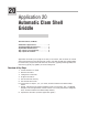
0 Application 20 Automatic Clam Shell Griddle Dual Heat Channels, Six Menus Introduction to Application 20 . . . . . . . . . . . . ....1 Configuration Mode Quick Reference . . . . . . . . . 3 Program Mode Quick Reference . . . . . . . . . . . . 4 Step 7 Design a Faceplate Overlay. . . . . . . . . . . 5 Step 8 Operate the Controller . . . . . . . . . . . . . .
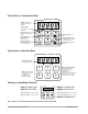
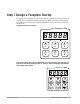
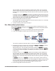
Key Functions in Configuration Mode MINICHEF 2000 Display five-digit, sevensegment numeric LED display. Indicator lights (1 for each key, 2 for heat channels). G H A Edit key (A) Access the next level of parameters or values. Enter key (B) Enter the value and return to previous level. Home key (D) Move to Operation Mode with a two-second key press. C B Edit Up key (C) Move up the lists. Enter D Home Escape key (E) Return to original value when editing a parameter value.
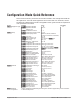
Configuration Mode Quick Reference These are the functions, parameters and values included in the Configuration Mode for this application. You must select Application 20 to access them. For directions, see the Hardware & Software Setup Guide. The Appendix of that guide includes an explanation of all parameters and values.
Program Mode Quick Reference These are the functions, parameters and values included in the Program Mode for this application. You must select Application 20 to access them. For menu programming directions, see the Hardware & Software Setup Guide. The Appendix of that guide includes a detailed explanation of all parameters and values. Function [M`--] Menu Numbers 1 - 6 Parameter [Stpt1] Set point 1 Temperature of channel 1. Setting Temp range low to temp range high. [TiNe1] Time 1 Menu run time.
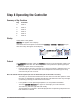
Step 7 Design a Faceplate Overlay To complete the installation, you must apply a graphic membrane to the front panel of the controller. The following artwork will help you design and create a membrane for this application. For more dimensions and guidelines, see the Hardware & Software Setup Guide.
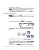
Step 8 Operating the Controller Summary of Key Functions Key Function A Menu 1 B Menu 2 C Menu 3 D Menu 4 E Menu 5 F Menu 6 Startup Apply power to the griddle. [`iDle] will appear on the display. If the Real-time Clock option is installed and [SetUp] / [CLoc`] = [``YES] the present time of day will appear on the display.
The heat output indicator lights (G & H, just below the display) will light up whenever the controller is calling for heat. When both channels are at operating temperature (set points minus the ready band) [ready] will appear on the display and the menu key indicator light will flash rapidly. You are now ready to cook with the active menu. If the griddle is at operating temperature, the display goes directly to [Ready] without indicating preheat or temperature.
will be emitted. The menu key indicator light will flash rapidly. You can acknowledge and silence the tone by pressing the active menu key, or it will automatically time out within 20 seconds and go into idle while the menu key indicator light flashes slowly. If Sound is set to 4 or 5, [``end] will appear on the display and the menu key indicator light will flash rapidly. You must acknowledge the audible tone by pressing the active menu key.
The controller will continue to regulate at the last set point that was run. The menu key indicator light will flash slowly. 5. To repeat cooking, repeat steps 1 through 4. Cancel a Menu Canceling a menu stops controller operation completely. The controller does not maintain set point temperatures or run time. You cancel a menu to run another menu, stop menu operation for any reason, or are preparing to shut off the griddle. • Press the active menu key for 2 seconds. Heat outputs will switch off.
Notes 10 ■ Watlow M I N I C H E F 2000 Application 20
21 Application 21 Manual Clam Shell Griddle Two Heat Channels Introduction to Application 21 . . . . . . . . . . . . . 11 Configuration Mode Quick Reference . . . . . . . . 13 Step 7 Design a Faceplate Overlay . . . . . . . . . . 15 Step 8 Operate the Controller . . . . . . . . . . . . . 16 Application 21 allows you to control cooking temperatures and cooking times using a clam shell griddle (two-sided griddle).
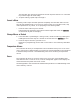
Key Functions in Configuration Mode MINICHEF 2000 Display five-digit, sevensegment numeric LED display. Indicator lights (1 for each key, 2 for heat channels). G A Edit key (A) Access the next level of parameters or values. Enter key (B) Enter the value and return to previous level. Home key (D) Move to Operation Mode with a two-second key press. H C B Edit Up key (C) Move up the lists. Enter D Home Escape key (E) Return to original value when editing a parameter value.
Configuration Mode Quick Reference These are the functions, parameters and values included in the Configuration Mode for this application. You must select Application 21 to access them. For directions, see the Hardware & Software Setup Guide. The Appendix of that guide includes an explanation of all parameters and values.
Auto-tuning Note: Before auto-tuning Application 21 for zone 1, [TeNp1] must first be set to a value that is typical for zone 1. (See the Hardware & Software Setup Guide for information on programming menus.) Then set [tHErL] / [tunE1] to [```on]. After you accept [```on], by pressing “Enter,” the controller will display [`tunE] while auto-tuning is taking place. Then you can auto-tune zone 2, by first setting [TeNp1] of Menu 1 to a value that is typical for zone 2. Then set [tHErL] / [tunE2] to [```on].
Step 7 Design a Faceplate Overlay To complete the installation, you must apply a graphic membrane to the front panel of the controller. The following artwork will help you design and create a membrane for this application. For more dimensions and guidelines, see the Hardware & Software Setup Guide.
Step 8 Operate the Controller Summary of Key Functions in Operation Mode Key Operation Function A Cook Temp(s) B Cook Time C Up (Increment) D Not Used E Start/Stop F Down (Decrement) Startup Apply power to the griddle. [`iDle] will appear on the display. If the Real-time Clock option is installed and [SetUp] / [CLoc`] = [``YES] the present time of day will appear on the display. Set the Menu Set the cooking temperatures. 1.
3. Press the Cook Time key again. The cooking time has been set. [`idle] will appear on the display. Five Second Timeout When using the up or down keys to change a value, if you do not press any key for 5 seconds, the controller will automatically be set to the last value on the display and return to [`idle].
3. With [ready] on the display, place the food on the bottom griddle, lower the top griddle, and press the Start/Stop key(indicated by the rapidly flashing indicator light).
tain set point temperatures or run time. You cancel a menu to run another menu, stop menu operation for any reason, or are preparing to shut off the griddle. • Press the Start/Stop for 2 seconds. Heat outputs will switch off. Heat output indicator lights will switch off. [`idle] or the time of day will be on display.
Notes 20 ■ Watlow M I N I C H E F 2000 Application 21
Application 22 Automatic One-Sided Griddle One Heat Channel, Six Menus Introduction to Application 22 . . . . . . . . . . . . . 21 Configuration Mode Quick Reference . . . . . . . . 23 Program Mode Quick Reference. . . . . . . . . . . . 24 Step 7 Design a Faceplate Overlay . . . . . . . . . . 25 Step 8 Operate the Controller . . . . . . . . . . . . . 26 Application 22 allows you to program as many as six menu keys to control one temperature channel and cooking time for an automatic one-sided griddle.
Key Functions in Configuration Mode MINICHEF 2000 Display five-digit, sevensegment numeric LED display. Indicator lights (1 for each key, 2 for heat channels). G H A Edit key (A) Access the next level of parameters or values. Enter key (B) Enter the value and return to previous level. Home key (D) Move to Operation Mode with a two-second key press. C B Edit Up key (C) Move up the lists. Enter D Home Escape key (E) Return to original value when editing a parameter value.
Configuration Mode Quick Reference These are the functions, parameters and values included in the Configuration Mode for this application. You must select Application 22 to access them. For directions, see the Hardware & Software Setup Guide. The Appendix of that guide includes an explanation of all parameters and values.
Program Mode Quick Reference These are the functions, parameters and values included in the Program Mode for this application. You must select Application 22 to access them. For menu programming directions, see the Hardware & Software Setup Guide. The Appendix of that guide includes a detailed explanation of all parameters and values. Function Parameter Value [M`__] Menu Numbers 1 - 6 [Stpt1] Set point 1 Temperature of set point 1.
Step 7 Design a Faceplate Overlay To complete the installation, you must apply a graphic membrane to the front panel of the controller. The following artwork will help you design and create a membrane for this application. For more dimensions and guidelines, see the Hardware & Software Setup Guide.
Step 8 Operate the Controller Summary of Key Functions in Operation Mode Key Function A Menu 1 B Menu 2 C Menu 3 D Menu 4 E Menu 5 F Menu 6 Startup Apply power to the griddle. [`iDle] will appear on the display. If the Real-time Clock option is installed and [SetUp] / [CLoc`] = [``YES] the present time of day will appear on the display.
The heat output indicator light (G, just below the display) will light up whenever the controller is calling for heat. When Channel 1 is at operating temperature (set point minus the ready band) [ready] will appear on the display and the menu key indicator light will flash rapidly. You are now ready to cook with the active menu. • If the griddle is at operating temperature, the display goes directly to [Ready] without indicating preheat or temperature.
es slowly. If Sound is set to 4 or 5, [``end] will appear on the display and the menu key indicator light will flash rapidly. You must acknowledge the audible tone by pressing the active menu key. Once acknowledged, the audible tone is silenced and the controller goes into idle.The menu key indicator light will flash slowly. 4. Remove the food from the griddle. The controller will continue to regulate at the last set point that was run. The menu key indicator light will flash slowly. 5.
Cancel a Menu Canceling a menu stops controller operation completely. The controller does not maintain set point temperatures or run time. You cancel a menu to run another menu, stop menu operation for any reason, or are preparing to shut off the griddle. • Press the active menu key for 2 seconds. The heat output will switch off. The heat output indicator light will switch off. [`idle] or the time of day will be on display. Change Menus or Restart 1.
Notes 30 ■ Watlow M I N I C H E F 2000 Application 22
23 Application 23 Manual One-Sided Griddle One Heat Channel Introduction to Application 23 . . . . . . . . . . . . . 31 Configuration Mode Quick Reference . . . . . . . . 33 Step 7 Design a Faceplate Overlay . . . . . . . . . . 35 Step 8 Operate the Controller . . . . . . . . . . . . . 36 Application 23 allows you to program a menu to control one temperature channel and cooking time for a manual one-sided griddle. Overview of Key Steps 1. Install the MINICHEF 2000. 2. Wire the controller. 3.
Key Functions in Configuration Mode MINICHEF 2000 Display five-digit, sevensegment numeric LED display. Indicator lights (1 for each key, 2 for heat channels). G A Edit key (A) Access the next level of parameters or values. Enter key (B) Enter the value and return to previous level. Home key (D) Move to Operation Mode with a two-second key press. H C B Edit Up key (C) Move up the lists. Enter D Home Escape key (E) Return to original value when editing a parameter value.
Configuration Mode Quick Reference These are the functions, parameters and values included in the Configuration Mode for this application. You must select Application 23 to access them. For directions, see the Hardware & Software Setup Guide. The Appendix of that guide includes an explanation of all parameters and values.
Auto-tuning Note: Before auto-tuning Application 23, [teNp1] in the operations menu must first be set to a value that is typical of your application (See the Hardware & Software Setup Guide for information on programming menus.). Then set [tHerl] / [tunE1] to [```on]. After you accept [```on], by pressing “Enter,” the controller will display [`tunE] while auto-tuning is taking place. The controller will cancel the auto-tuning process if it cannot be completed in 80 minutes.
Step 7 Design a Faceplate Overlay To complete the installation, you must apply a graphic membrane to the front panel of the controller. The following artwork will help you design and create a membrane for this application. For more dimensions and guidelines, see the Hardware & Software Setup Guide.
Step 8 Operate the Controller Summary of Key Functions in Operation Mode Key Operation Function A Cook Temp B Cook Time C Up (Increment) D Not Used E Start/Stop F Down (Decrement) Startup Apply power to the griddle. [`iDle] will appear on the display. If the Real-time Clock option is installed and [SetUp] /[CLoc`] = [``YES] the present time of day will appear on the display. Set the Menu Set the cooking temperatures. 1.
3. Press the Cook Time key again. The cooking time has been set. [`idle] will appear on the display. Five Second Timeout When using the up or down keys to change a value, if you do not press any key for 5 seconds, the controller will automatically be set to the last value on the display and return to [`idle].
3. With [ready] on the display, place the food on the griddle and press the Start/Stop key(indicated by the rapidly flashing indicator light).
Changes can be made to temperature and time only during the portion of the cooking sequence in which they are active. For example: a change to the first cooking temperature [tENP1] can be made only when the first cooking temperature is being run during the cooking sequence. Temperature changes made while cooking are saved and become part of the permanent menu. Time changes are not saved and do not become part of the permanent menu. Cancel a Menu Canceling a menu stops controller operation completely.
Specifications (1032) Control Mode 1 • Single and dual heat channels, PID or on/off. • Microprocessor-based, programmable, reverse-acting control outputs. • User-selectable embedded application software defines operation of display, keys, inputs, outputs, timing action. • One-step auto-tuning, WatHelp diagnostics, WatCurve temperature compensation.
Ordering Information (1033) F 2 HA- _ _ _ 1 - _ _AA MINICHEF™ 2000 Cooking controller with numerous food equipment application software sets, single and dual channel on/off or PID temperature regulation, timer and machine-function control, microprocessorbased, programmable, auto-tuning, WatCurve, WatHelp diagnostics, 24VÅ (ac) power input, agency approved, flush mounted (membrane faceplate supplied by customer).
Ordering Information: Part Numbers & Accessories MINICHEF 2000 Accessories MINICHEF 2000 Documentation 0836-0442-0000 WMC2-XUGN-0000 A001-0298-0000 0238-0679-0000 0830-0479-0000 A001-0249-0001 A001-0249-0002 Sensor Input Mating Connector, (RIACON #31007106), 6-position, quick-connect terminal, screw connection for 28-14 AWG wires, tighten to 7 in/lb Power Supply and I / O Mating Connector Kit.
Watlow Controls Watlow Controls is a division of Watlow Electric Mfg. Co., St. Louis, Missouri, a manufacturer of industrial electric heating products since 1922. Watlow begins with a full set of specifications and completes an industrial product that is manufactured totally inhouse, in the U.S.A. Watlow products include electric heaters, sensors, controls and switching devices.
Notes 44 ■ Watlow M I N I C H E F 2000 Application 23
Watlow MINICHEF™ 2000 Griddle Applications Guide Watlow Controls, 1241 Bundy Blvd., P.O. Box 5580, Winona, MN U.S.A.